Info Projectors
RESOLUTIE VERSUS CONTRAST
Often, one has a dilemma to make a choice between projectors with better resolution or better contrast.
The most cockpitbouwers with a 225° FOV-setup and 3 beamers opt for the better resolution (FullHD). A projector with a higher contrast is always a good thing.
The contrast of current DLP projectors meets but LCD projectors have a higher contrast. The disadvantage again is that LCD projectors during a night flight and the black not completely black but gray.
The use of a higher resolution is that you often have to compromise on frame rates ...
NATIVE RESOLUTION AND MAXIMUM RESOLUTION
Often there is confusion between native resolution and maximum resolution, and the use thereof.
Why these 2 specifications and what is actually the difference ?
It is actually pretty easy. Each projector is composed of microdisplays, whether it's LCD, DLP or LCOS chips. On these microdisplays is a fixed set of pixels. That fixed array of pixels is known as the native resolution of the projector. So native resolution is the actual, true, physical resolution of the projector. The projector will never be able to do more actual pixels to display than that on the microdisplays or chips.
So then, what is the maximum resolution?
This value has nothing to do with the physical display of the projector. Instead, it has to do with the signaalformaten.
Computer and video signals come in a wide range of resolutieformaten. And every projector is programmed to a lot of different signals to recognize. Maximum resolution is the highest resolutiesignaal that the projector is programmed for processing and displaying.
When a projector a signal that does not match its native resolution, should that signal be converted to the format of the native resolution to display correctly. This conversion process is often referred to as scale enlargement/reduction (scaling).
So for example, let's assume that you have a video projector with a native resolution of 1280×800 and the display of an HDTV 1080i signal. That means that the physical pixel of the projector matrix is 1280 pixels wide and 800 pixels high. However, each frame of a video in HDTV 1080i signal contains 1920×1080 pixels, which is much more than the projector on the physical display. So in order for the 1080i signal to display through the projector must compress it in a 1280×800 size. The projector is able to do this because it is programmed to have the compression to do from 1920×1080 to 1280×800. The maximum resolution would be a “scalled image” again in the native resolution.
So if 1920×1080 is the highest resolution that the projector is programmed to recognize and compress in its native display is 1920×1080 known as the maximum resolution of this projector.
It is therefore recommended that the ‘native resolution’.
NVIDIA INSPECTOR
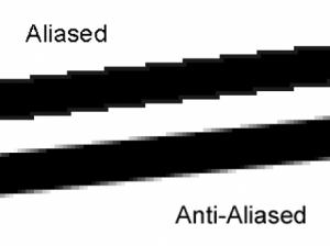
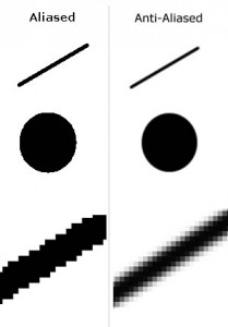
Especially the outlines or contours of an object, such as in an aircraft or runway are not always nicely delineated. These are usually jagged or in trapvorm (jagged).
To this problem really to address there must be doctored to the ANTI-ALIASING.
Anti-Aliasing you can check in FS but returns often to little result.
A better result one obtains by the settings of the video card to change. This can directly be done via the Control Panel of the video card or through programmes such as nHancer or NVidia Inspector.
nHancer is limited to Nvidia-drivers to 25x.xx. For Nvidia-drivers with a higher number (so from 257.21) is Nvidia Inspector suitable.
NHancer and Nvidia Inspector are useful applications that the driver and hardware information reads the GeForce cards. Only suitable for Nvidia-drivers.
With these tools, you may get the GF card to your hand and so also the settings that are useful for FS9 or FSX.
In the Nvidia Inspector there is an extra ‘feature’ to the GF card and overclocking.
How to use it for FS9 or FSX ?
- Download Nvidia Inspector (v1.959) and unzip in a random folder;
- Create a shortcut in the desktop;
- Run NvidiaInspector.exe (not necessary to first via your Nvidia Control Panel something to click on terms of D3D);
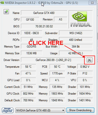
- Click on the like button below is indicated;
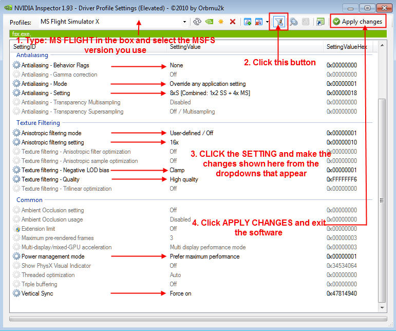
- Type at the top of the Profile box in the "MS Flight" and click on the arrow next to the box (see below). This brings you to a list with oa. MS FLIGHT SIMULATOR 2004 and MS FLIGHT SIMULATOR X. Select the correct FS (also, for example, P3D);
- Make the following changes as shown on the drawing. These settings do not change to other profiles, but only for FS9 or FSX (according to choice);
When everything is set, click on the ‘APPLY PROFILE’;
Make sure that in FSX ‘Anti-Aliasing’ (AA) is unchecked, and set Fliltering’, ‘Trillinear’.
Note :
If you want 8xSQ, or another AA-level is the simple ANTIALIASING -SETTING to choose, and then make a choice in the dropdown box.
8xS and above check the ‘Autogen SHIMMER’ (flicker) and the quality of VC cockpits with high-end aircraft.
In a 225° FOV-setup works, it is usually in FSX in “full screen”mode.
CALCULATORS
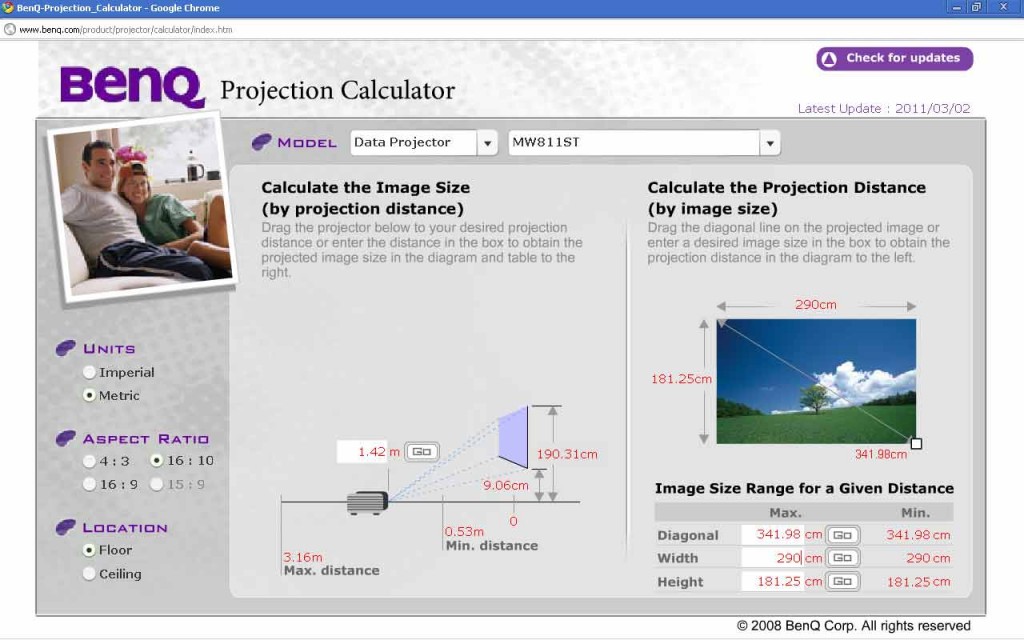
A useful tool to help you in the choice of a projector is the use of the Calculator;
This online tool is found at different projectorproducenten where there are different distances, you can calculate and for each orientation of the projector.
So can calculate which projector best fits the available space.
*** BenQ Calculator ***
*** Projector Calculator for different brands and types ***
PROJECTOR SETUP
For that one goes to the choice of a projector is important, planning. D. w.z. to start with a drawing of the projection space or cockpitroom and different measurements to do :
- Distance from viewpoint to projection area (radius);
- Distance lens to a projection screen;
- Projection angle from the projector to a projection screen (FOV = Field of view);
- Available projection screen in width and height;
- Place of the projector's lens (remember that the projector is larger than just the lens ...).
- Cockpit physical point of view = FS9(X) software point of view !
With this information, it is much easier to make a choice for a suitable projector.
225° FOV VISUAL SYSTEM
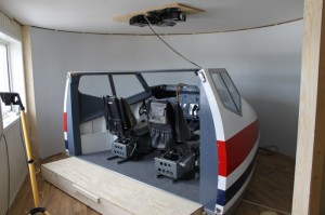
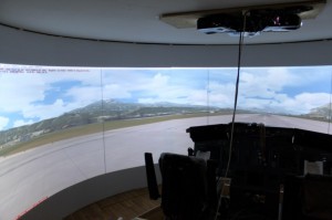
When you have enough space available and enough money maybe you can extract with a 225° FOV visual system. M. a.w. a 225 degree projection area (= field of view) which one to rear-left and rear-right look.
It uses 3 projectors, a 225° curved screen and Warping software. This warping software should be to the projected images on the curved screen to project.
The ‘warping’ and ‘blending’ software that most are used for this purpose FlyElise and NatVis. Both are among the best in their class
*** Download manual 225° Visual System ***
CRABBING/SIDESLIPPING EFFECT
M. a.w. when you am pretty lined up with the runway (e.g. in final and without wind) or diagonally (in the crab) to the runway fly.
In order to solve this problem you can a few adjustments in the panel.cfg of the plane.
You have 3 possibilities :
1. The image is OK from the Capt seat, but a ‘crabbing’-image from the F/O seat;
or
2. We have a ‘crabbing’image on both sides;
or
3. The image is OK from the F/O chair but with a ‘crabbing’-image from the Capt seat.
This is checked with VIEW_FORWARD_EYE and VIEW_FORWARD_DIR under the [VIEW]header in the panel.cfg of the plane.
The values below are the values I've used in FS9 for a correct JETSTREAM 737-800 CAPT chair and this without ‘Crabbing’. These values can be used as a reference for other setups. It is also the intention what to ‘play’ with the stated values so that one may get an optimal image.
//Move eyepoint: Left/Right (neg – left), Up/Down (neg – down), Forward/Back (t – back)
VIEW_FORWARD_EYE=-1.0, 1.0, 0,0
//Rotate view in Pitch (Up – nec), Roll (Left neg), Heading (Left – neg)
VIEW_FORWARD_DIR=0.0, 0.0, 5.0
The ‘Crabbing’-problem can also be reduced by continuing to sit of the projection display or the zoom to reduce it to .35 or .40. The hardware can also be improved by the projector to move to the left or to the right.
THE WHITE PIXELS IN THE DISPLAY
After 7 years you can projector the well-known beamerziekte get, on the projected image there are white dots or pixels to see.
In the beginning, there are only a few but after a period of time, there are dozens, hundreds, thousands ... The most cockpitbouwers that a DLP projector have (any brand) will get here usually.
This indicates a defective DMD-chip. This chip from Texas Instruments " is made up of millions of micro-mirrors that for a projected image concerns. By too much heat can these mirrors no longer tilt and fall consequently, one by one. The result is all white dots (also black) in the display. Each white dot represents a pixel.
Can you prevent this? By the beamer sufficient cooling to give by a fan to convert and if the projector hangs from the ceiling, where the warm, this a minimum of one 15 à 20 cm from the ceiling hang.
Restore? You can use the projector-entry for repair and the DMD chip replaced. But that is an expensive affair. Average cost for a DMD-repair : +- €600. Then you have that money almost a new projector...
You can repair yourself, and then you pay just the cost of a new DMD chip. Cost +- €220.
So replacement is the message. And this job is not so difficult to carry out.
On Youtube there are several videos to see how they explain how to get a DMD chip need to be replaced. Of course every projector of his own construction.
I direct me to the videos where they find a BenQ-projector hands. Here I've added a link how to get a DMD chip for a BenQ projector needs to be replaced.
http://www.perfectbuys.net/projector-dmd-chip-replacing-tutorial
The DMD chip behind the lens and just before a metal block with cooling fins. The DMD chip is located in a separate printed circuit board (pcb).
First the plastic cover on the top will be removed, and this together with the back where the connections are located. Then is the turn for the full "belly" of the projector is blank. Before and after each operation I have photos taken of the whole, or parts, and then it will not have any problems to get to putting it back together of the various components.
The important thing is the full block with circuit boards to removethereafter the built-in fan or koelingsfan and then the metal block with cooling fins. Then rest there only printed circuit board with DMD chip from the slot pull.
The new DMD chip I have purchased from Vervangjelamp.nl. They have a wide choice and excellent and fast service.
Translated by Yandex.Translate and Global Translator
