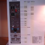
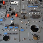
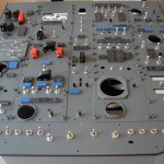
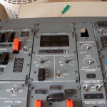
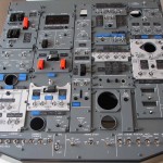
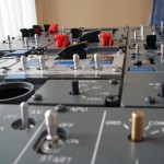
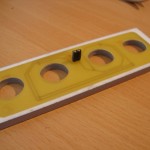
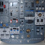
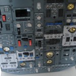
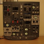
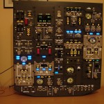
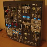
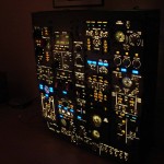
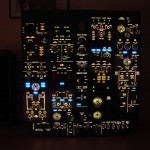
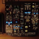
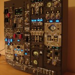
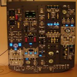
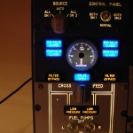
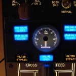
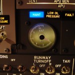
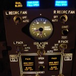
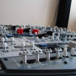
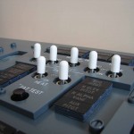
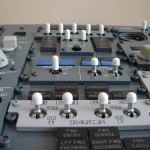
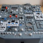
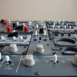
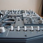
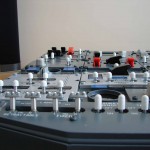
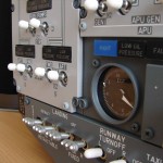
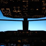
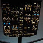
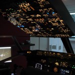
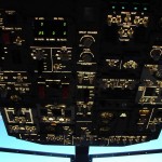
Forward Overhead
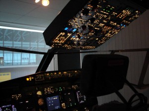
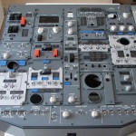
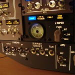
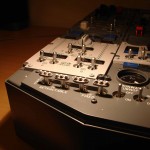
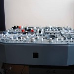
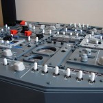
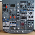
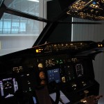
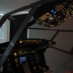
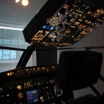
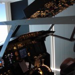
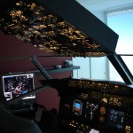
The overhead is the rectangular console or panel with the various switches and lights up in the cockpit.
The overhead together with ProSim are the nerve centre of the aircraft from which all systems are activated and checked.
Here you can two overheads are distinguished : the forward and the after overhead.
Building, connecting wiring and interfacing are one of the most complex tasks in building a cockpit and is regularly underestimated.
WHERE TO BUY AND WHAT ?
When you use the Internet browses or visit us at the FSWeekend in Lelystad you come across various manufacturers that a OVH in their product line. Choice enough ...
You can already start to filter through questions such as :
- What is realism and what quality do you want?
- For any interfacesysteem do you choose ?
- Reliability and service from the manufacturer ?
- What is the price tag and the available budget ?
Realism and quality
The firms that are very good quality and high realism pursue his unspoken FlyEngravity from the Netherlands and Flight Deck Solutions from Canada.
Especially to pay attention to the correct color, thickness and finish of the panels, annunciators, types of switches and buttons.
Also the variety of choices that one has in the various components is also not negligible. As the various switches and buttons, and whether or not the internal backlighting of the panels.
Reliability and service
This is also an aspect that is not unimportant. A damaged or incomplete order in receive take is not pleasant. A lot of euro's changed hands and something which is beyond expectations, has no half or getting answers to their emails ...... All things that can happen and that we can miss.
Therefore, it is recommended to do the necessary research to do before you proceed to order. Lot see photos, forums, a protein skimmer, experiences obtained from other cockpitbouwers.
Price tag and available superb
This should just about the largest filter. This has a lot of chaff from the wheat separate.
You have very little superb, and the realism should be something less, then you can choose for Opencockpits.
You put the bar very high terms of realism ? If you do not like a challenge or failure ? You may be lazy and find the easiest way ? Or do you have a well-filled purse, then it is ICS the right solution.
You fall between the two solutions, and if you want a mixture of components and interface systems, then the pocket calculator referee should play...
A golden rule is to examine what your best chance at success. Which components you use (cheap or expensive), it should afterwards function !
.
Taking into account the different facets that are named, I for my OVH back in the boat, and the stepped parts of FlyEngravity :
- Realistic and beautifully finished;
- Good experiences with my MIP (also from FlyEngravity);
- PEB panels (integrated backlighting – Easy Panel Backlighting) – MIP has the same EPB panels and the view is spectacular;
- Electronic kit (switches, buttons) realistic and everything fits in the panels;
On my schedule for the interfacing of the OVH were normally 3 or 6 Pokeyskaarten for the inputs (switches) and 2 Phidgets64 LEDS for the annunciators.
Along with Prosim, this is one of the most simple and ecomomische ways to interface.
But it is otherwise turned down. During a visit to the FlyEngravity stand during the FSWeekend 2011 I got a ICS-offer (Integrated Cockpit Systems), after some calculations, cheap came out with the Pokeys and Phidgets.
The big advantage to ICS is that there are no switches and annunciators (leds) to be mounted, no soldering, no wiring, no suitable displays to locate and install. Everything is already provided on the ICS-pcb's. And not to mention also no interface to implement. Everything is already ingrained in the ICS system.
This OVH is not equipped with the Honeywell switches, but with the APEM-switches (also locking liver switches but less "real" and cheaper). For the rest of the implementation is the same as any other ICS OVH.
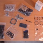
COMPOSITION
The parts of my overhead come from FlyEngravity and is composed of :
- PEB frame;
- ICS pcb with switches;
- Annunciator holders with legends;
- EPB panels;
- Displays;
- Buttons;
- Coverbox PEB frame;
- Bezels and decals;
- Power Supply.
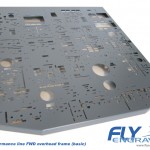
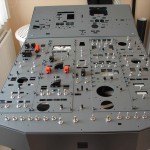
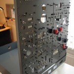
ICS PEB Frame
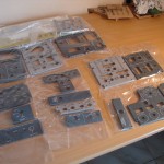
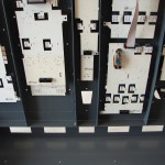
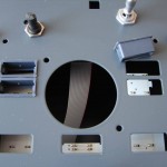
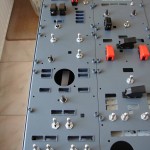
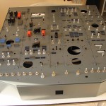
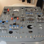
This is the metal framework on which everything is mounted, such as the ICS-pcb with switches, annunciators, panels, gauges, displays, and decals. All the openings on this frame already.
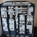
ICS Pcbs
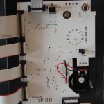
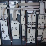
These are the circuit boards on the back of the frame to be installed. The FWD-OVH consists of 10 pcbs of which one motherboard. All other pcbs are connected to this board (daisy-chain).
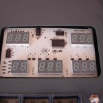
The ICS-pcb equipped with Smd-leds (annunciators), APEM switches and displays such as AC/DC and Pressurization Displays (Cruise FL and the Airport Alt).
Annunciator holders with legends
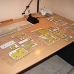
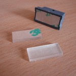
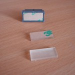
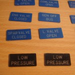
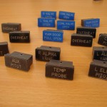
This 101 annunciator holders (housing of the annunciator or indicators) are composed of 4 parts : external holder, single holder, transparent self-adhesive plate in plexiglass and the picture with the inscription (legend).
EPB Panels
PEB panels (Easy Panel Backlighting) are equipped with a built-in backlight system, and the back features a integrated board with Smd-leds. Also on this board there is a connector to connect to the ICS-pcb's.
The FWD OVH is equipped with 17 panels of each 6 mm thickness. The panel of the Voice Recorder is not equipped with backlighting, and is also thinner.
Displays
The 2 displays are different digital read-outmodules found on the FWD OVH.
Distinction is the Pressurization Display (Cruise FL and Airport Alt) and the AC/DC Display.
Both are already mounted on a ICS-pcb.
Gauges
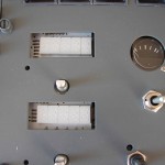
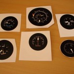
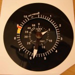
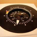
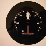
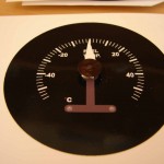
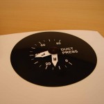
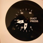
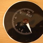
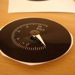
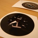
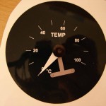
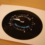
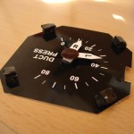
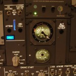
The gauges are the different meterjes on the FWD OVH. For the moment, the openings of the meters filled up with ‘decals’ or stickers. In the future, be replaced by meters of Flight Illusion.
The gauges are composed of :
- Cabin Climb
- Cabin temperature
- Oxygen pressure
- Duct pressure
- Fuel temperature
- EGT
- Differential pressure/cabin alt
Buttons
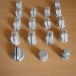
The ICS-OVH comes with 14 Boeing Style buttons, 2 round buttons for the Pressurization display, and the big round button for the fuel cross feed.
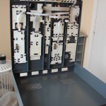
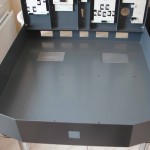
Coverbox
The coverbox is the ‘box’ in which the OVH-frame is mounted. The frame is so attached that this is for work inside at the front can detach and openkantelen to the bottom.
The coverbox is in turn attached to an overhead/shell construction made of wood or metal pipes.
Bezels and Decals
Any stickers that one here and there can make for quite the matter a bit more realistic.
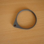
The bezels are the rings around the openings for the gauges.
Power Supply
These ICS OVH is equipped with a Power Adapter of 12 Volts and a USB connection.
ASSEMBLY OVERHEAD
Normally is an ICS version and ready to delivered but on this there was still some work to be done :
- In other tinkering of the annunciator holders (101 pieces), and mounting in the frame;
- Install the EPB panels and each panel connecting to the ICS-pcb's;
- Places of the bezels;
- Locating and fixing the buttons;
- In the openings of the meters, the decals to place (optional);
- The decals come with backlighting (optional).
The big advantage to ICS is that there are no switches and annunciators (leds) to be mounted, no soldering, no wiring, no displays, search for and install. Everything is already provided on the ICS-pcb's.
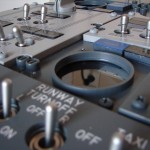
This OVH is already equipped with realistic APEM switches magnetic switch (Solenoids) for the ‘yaw damper’ and ‘anti-ice’ and ‘automatic jump back’ switches for the start buttons.
PEB Frame and ICS Pcbs
I have the frame in reception is obtained with the ICS-pcb's have already been fitted were on the back of the frame. On these ICS, pcbs were also all the switches and the displays.
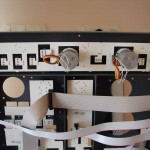
The circuit boards are ‘daisy chain’ with flat cables connected to each other .
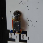
For the ‘Yaw Damper’ and the ‘ Wing Anti-Ice " switches are magnetic switches or Solenoids. What are ‘Solenoids’ ?
The principle of a Solenoid is very simple, it is a coil wrapped around a round tube. Inside that tube is for 2/3 a pin of slightly less diameter as the diameter of the round tube. A part of that pin is sticking out and at the end you make something (battery or switch), then a spring between the part that sticks out and the solenoid house.
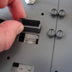
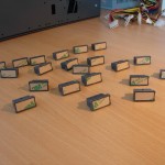
Only the annunciator holders (housing) must have in each other geknutselt and on the frame in the openings be pricked. The leds are already on the ICS-pcb's. This annunciator holders come just above the leds to sit in.
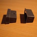
The annunciator holder is composed of 4 parts :
- External holder;
- Internal holder;
- Transparent plexiplaatje to one side of the adhesive layer;
- Picture with the caption (legend).
First, the external holders in the openings of the frame. These go on very easily and are loose in the openings;
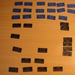
To find out which caption goes where, you can on the FlyEngravity-site the right download images.
The bezels or the kunststofringen, which is also in the package, to be on (around) the openings of the gauges placed. Each ring is on the back with self-adhesive foil.
Mount PEB panels
This was just the 18 panels (17 EPB +1 Voice Recorder) on the frame and screw tight with the enclosed screws. Sometimes there was a problem with some spring clips of a switch in the way so that the panel is not completely flat could be laid. A little bit of the corners afvijlen of the relevant bevestingsring was enough omhet to solve the problem.
Also the spring clips from the 2 Automatic Jumpback’-switches (Start Switches)were too thick. Which I replaced by thinner ones.
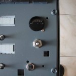
On the back of the ‘Voice Recorder’ panel, there were also no notches or recesses provided for the bevestigingsringetjes of the 2 small micro switches. With the dremel I have both cutouts than to route out.
On the frame were left and right a few small holes not pre-drilled for the mounting of the panels.
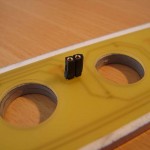
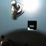
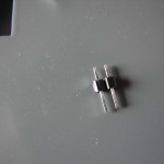
All EPB panels on the back with a connector that must be connected to the connector on the ICS-pcb. These connectors serve for the backlighting. To the distance between the two connectors to bridge has FlyEngravity verbindingsstekkers with you on the correct size or distance should be cut off and between the two connectors.
This album was what ‘good luck’ prikwerk. The pins must be correct in the 2 holes of the connectors and from the rear you can that it is difficult or not.
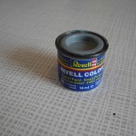
Afterwards, the fixing screws of the panels with a white-gray color (Fuel pumps, Gen Bus Trans, Hyd pumps and air-Conditioning) in the same color will be painted. I have to paint from the model Revell Color SM 374.
For the other screws is the standard Boeing-color (RAL7011), or for me Levis color code ACC R6.06.30.
Locating and fixing the buttons
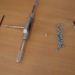
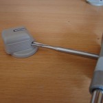
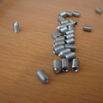
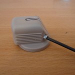
For the anchoring of the 14 Boeing Style buttons: they were not yet madeschroeven (bolts). To all of the buttons to the switches I have on 2 sides of the buttons, a small hole drilled 3.2 mm. I then in this opening is a wire tapped from 4 mm. Afterwards, just a madeschroef (bolt or screw) 4 mm thick and 6 mm long it turned to the button to anchor the shaft of the switch.
The madeschroeven (adjusting screws) I purchased at Fabory in Lommel, belgium. This company is specialized in the sale of all of the possible fasteners.
The 2 round buttons for the Pressurization display, " and the separate round button for the fuel cross feed were already equipped with maadschroeven.
Gauge decals
To the openings of the meters (gauges) to fill, I have provisionally made use of images. In the future, be replaced by meters of Flight Illusion.
These images are available for download on the website of FlyEngravity or via the link below. I have these images printed out on photo paper and are all cut to size so that they are behind the openings fit. The meters I have provided a needle to the what is, however, to make it seem. I then with a little bit of relief on the achtzijde pasted. I did this with double-sided adhesive tape is used of 2 mm thickness that I into small cubes 3x the thickness at the 4 corners have stuck.
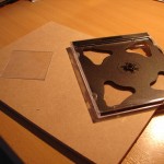
The openings in the frame, I provide a transparent plate (perspex). This ‘plexiglass’ is carved out of unused CD cases.
*** Decal set Forwoard Overhead ***
The images are :
- Cabin Climb
- Cabin temperature
- Oxygen pressure
- Duct pressure
- Fuel temperature
- EGT
- Differential pressure/cabin alt
Backlighting Gauge-decals
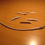
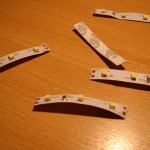
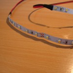
To the gauge-decals a bit more to bring it to life I have on the back for what backlighting taken care of. For this I led strips with Smd leds uses 12V.Each segment of these strips consists of 3 leds. You can just order the 5 cmcut. Per gauge-decal I have one segmentje of 3 leds are used, except for the differential pressure/cabin alt where I have 6 leds I used.
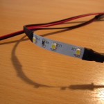
Each ledsegment is at both ends with + and – point of contact to which the wire can be soldered.
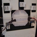
The assembly of the ledsegmenten on the back of the frame is done via a plexiglasstrip of 2cm between the ribs of the frame is confirmed (14,7 cm). I did this with brackets used that I have double-sided adhesive tape (2 mm thickness) and that against the frameribben are stuck. The plexiglasstrips are also attached to the brackets with the same tape. This tape attaches very well and is subsequently easy to remove (when the FlightIllusion-instruments in the place to come ...).
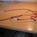
Each ledsegment I have then connected (daisy chain). The + and – contacts, I have insulated with a piece of shrink tube. The power supply is done via a pc-power supply. When the overhead will be built into the cockpit will this gauge-backlighting controlled via the backlightcontroller of FlyEngravity. Currently there is already the gauge-backlighting of the MIP connected to it (dimming). This controller features 3 channels which one per channel 7 circuitscan on connect.
The led strips are on the back equipped as standard with a 3M-adhesive tape for easy to stick it on the plexi plates.
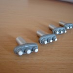
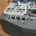
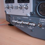
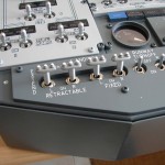
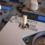
Landing lights toggle switch caps
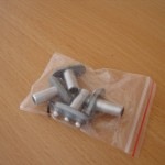
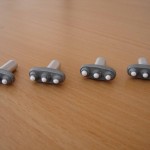
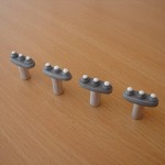
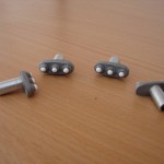
The " landing lights toggle switch caps I ordered from GLB Flight Products.
The caps that are on their website are only suitable for switch shafts are of max 3 mm. A little too small for my landingswitchen because they are from the top 5 mm and bottom 4 mm. Without additional price increase Geremy Britton custom made shaft made so it fit on my landingswitchen.
A set consists of 4 caps. The shaft is made from aluminium and the top part with the 3 scoops out of plastic. They are nicely made but the paint was a little more sophisticated, be done.
The switch caps can also be ordered with a rubber sleeve in the shaft (I knew not), so they are easy to attach to the switch.
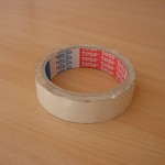
My switch caps I've confirmed with paper tape that they use for masking when painting in the house. Small strips of tape of 6 cm I have around the switch rotated until the switch everywhere a uniform thickness of had plus a little more to the shaft of the switch cap over it to rotate and so that it is firmly seated.
The aluminum shaft I have in the inside at the end a little afgevijld because the edge is a little to the inside. That edge interferes with the frame of the shaft on the switch. When the switch cap sits on it, you can, of course, have to turn left or right but completely fixed will be difficult. ... You can also try it with a shrink tube.
Paste ? But I fear that they will not separate, etc.
The future will show whether this confirmation with papiertape is OK. We test it out.
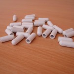
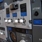
White caps to about the rockers to place
The APEM-switches are not equipped with white caps (hats). The Honeywell switch is provided.
So it is ourselves to figure out which caps can be applied to both the ordinary rocker switches as with the big ‘locking liver’ types.
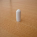
FlyEngravity has given me what units concerned and of them was the long, narrow cap of 21 mm is the most suitable. This is for the long switches as the big ‘locking liver’types.
This long cover has a size of 21 mm long and a thickness of 8 mm. The standard is 5 mm.
21 mm is a bit too long therefore they have to be cut to size. For long switches have a height of 18 mm held and for the ‘locking liver types 9 à 10 mm.
When you place the cap on a long switch slide, there is still quite a bit of clearance and that should so what be filled so that the cap is seated properly.
First I tried it with a shrink tube but that is easy to disconnect. Ideal is regular paper schildertape to use. This tape turns easily around the switch and you can experimeteren with different thicknesses. The white cover slides easily over it, and is afterwards sufficient.
In the ‘locking liver-switches, you don't have paper tape to use. The carved cap of 9 mm put so are already well fixed around the spherical switch.
In the cut is a bit to pay attention that the cap perfectly straight cuts. I did use a metal ruler including the rubber cap is flat is pressed and so on the edge is cut off with a utility knife.
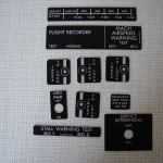
Black aluminum decals
The decals bstaan 5 black aluminiumplaatjes with white text. These decals are also from FlyEngravity.
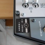
- 2 x Index To Lock – left, and bottom right where the sluitingsboutjes to the OVH to open and close;
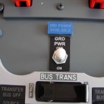
- GND PWR ON/OFF GND PWR switch;
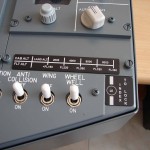
- Cab Alt / Flt Alt at the Bottom right above the Light-switches;
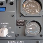
- Press Diff Limit – to the left of the " Cabin Climb’-gauge.
These decals are attached with double-sided tape.
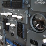
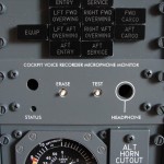
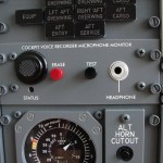
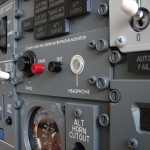
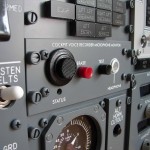
Cockpit Voice Recorder
The CVR panel in the FWD Overhead has no function in a simcockpit. That don't want to say that we have this panel unterminated. That extra level of realism is part of it...
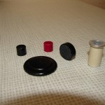
The backplate of the microphone I made of a cover, in which contact lenses are stored. I have this lid to the half-cut and satin-black painted. I have this picture with double-sided tape pasted on the OVH panel. It is a little bulb and looks like the real thing.
On top of this achterplaatje I actually mircrofoontje pasted. That you can e.g. create a waterkraanroostertje kitchen or bathroom (not the kitchen stripping hey...).
The pressure switches (Eras and Test) I have equipped with a black and red button (Conrad.be – 10 mm x 8.5 mm). These pressure switches were all provided and is connected to the ICS-pcb. Ditto for the green led (Status).
The headphone hole I have filled with a dummy adapter (comes from FlyEngravity).
You can do this, maybe also a jack adaptor to use.
In a real 737, is the test button for a diagnostic test. The status led lights up briefly and you will hear a sound when you connect the headphones.
The Eras-switch erases the CVR.
Forward Overhead operational
After the tinkering of the metal frame to which the overheads need to come hang out, and the confirmation of the FWD Overhead is the time to get this operational.
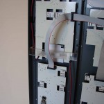
The cable routing goes through the metal bracket of 80 mm. This is for the 12V-power supply with adapter (which I extended to do), the cable of the backlightverlichting of the dummy gauges, the ICS USB cable and the cable of the overhead spotlight’ (Flood light).
The cable of the backlightverlichting I have connected to the ‘FlyEngravity backlight controller " and this on the same channel that I have the dummy gauges (MIP standby instruments ) adjustment.
The ICS USB cable is connected to the FS/Prosim-pc, the USB device by windows to configure, and as the last in ProSim (drivers – FlyEngravity ICS Overhead) the correct COM port (COM8). And the christmas tree begins to burn ...
Further configuration of switches and indicators is not necessary since the ICS system and ProSim737 are geared to each other by the voorprogrammatie in ProSim737.
.
Translated by Yandex.Translate and Global Translator
