The Standby Instruments
DESCRIPTION:
The stand-by instruments are to serve as a back-up in case of a fault, or a X-check of the PFD and the ND (DU, s).
In the MIP of the B737-800 has three (or two), stand-by instruments.
The three instruments used for the analog version and 2 tools of the digital version. Be the first to Stby instrument, which is then covered with a plate.
The newer B737-800's (NG's) have become more and more equipped with, a digital version of it.
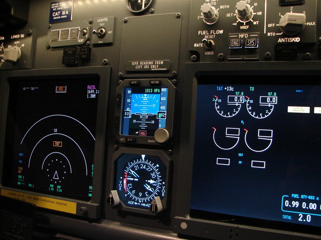
The standby instruments are located between the Upper Eicas and the EN s of the Capt.
: ANALOGUE OR DIGITAL ?
As has already been stated, there are 2 options for the MIP to be provided by the standby instruments, a choice between, on the one analog or the digital version.
In spite of the wide range of hardware-from the various handware-supplies, I would have a preference for the instruments of the
Flight Illusion. The main reasons for this are that the holes in my FlyEngravity-MIP with FI gauges. Also, since it's nicely finished instruments, and also due to the convenient terms and conditions.
The analog standby), instructor, Flight Illusion – original version
In the " old " version, stby instr of the internet is composed of a blue, black, attitude indicator, an altitude gauge and a digital display, and a 450 kts IAS gauge, with or without the ‘barberpole’.
I've got some research to do but for the last 2 gauges in the a INTERNET version, are nowhere to be found in a real B737-800 .... ? So it is not the right choice.
The analog Standby), Instructor, Flight Illusion – new version
The new stby instructor of your choice, have an in-depth change is required :
The attitude indicator is now more rounded instead of flat, and the altitude gauge is now up to a combined memory capacity of IAS and the Altitude is such that it is in the real Boeing 737 aircraft. The speedometer needle has been replaced by a RMI gauge.
The three analog gauges are a very realistich and a beautifully detailed finish.
Only the cost of the three-stby instruments is beyond the scope of my budget (+-1200 euros.
The digital gauge(s)
The question can be asked whether or not I have my cockpit, it may also be equipped with a digital stby gauges, such as those found in the current B737-800's ? In a digital implementation, the opening in the top of the Attitude indicator (kpi) is closed by a plate.
It is a display of the ISFD (Integrated Standby Flight Display) and the ISIS (Intergrated Standby Instrument System). This is a mini-version of the REQUIREMENT that the speed, the altitude, the air pressure can be read.
It is the second stand-by instructor below is a standard that ENABLES. It can also be replaced by a digital version, is to use the Prosim ENABLES the Display module. We found that the price for the most part.
Digital gauges to use, there are a number of questions were put forward with the additional steps :
- The current bezels on the MIPS need to be replaced. Where can I get the proper bezels + spare parts ?
- These bezels, but with the current holes in the MIP ?
- To fit these bezels with the TFT LCD display screens that will be behind the MIP is put in place ?
- In what should be the size of this TFT LCD display screens to meet to pass through any of the bezels installed ?
- Where can I get the TFT LCD monitors to buy ?
- It Is to be behind the MIP is enough space to have 2 of these units to place, both in width and in length ?
- Can I use 2 displays on top of each other where the edges of the screens are visible behind the bezels ?
- How do I change the color TFT-LCD display with A/D and D / a Board (controller card), attach to the back of the MIP ?
- There are still plenty of VGA video connections to the various cockpitcomputers ?
- The displays are rotated ?
- What is the price of it ?
CONCLUSION
In spite of this, many of the questions and problems I have to all of these questions have a positive answer, and I have decided to get the MIP can be equipped with 2 digital stand-by instruments, i.e., the ISFD and the RMI.
It's the price that's the deciding factor has to be given. For a full price-tag for the digital version is +- 280 euro. A big difference compared to the analog version (1200 €).
Another reason to switch to digital is that more and more of a real B737-800's will be fitted with a digital version of it.
Here I have to tell you that I am the knoppeninterface on the bezels not to have been left, as I still rarely will use it. Except, of course, if you have the necessary ‘failures’ are going to be simulated and that it was not yet meant to be.
One reason is that the inclusion of the various controls (dedicated switches into the bezels to be precarious.
The COMPOSITION
What hardware are stand-by instruments, consisting of :
- ISFD bezel with blank buttons
Of the ISFD-insert, I bought it for Sismo Soluciones. The size around the bezel to cover the gap in the MIP, and the inner dimensions of the bezelopening are consistent with the available displayoppervlakte of the color TFT-LCD screen;
- RMI bezel
In this insert I have I bought from Sismo Soluciones. In this insert, the inner and the outer dimensions are equivalent to the MIP-gaps, and is also available displayoppervlakte on the LCD screen. Both of the bezels are provided with donkergetint acrylic;
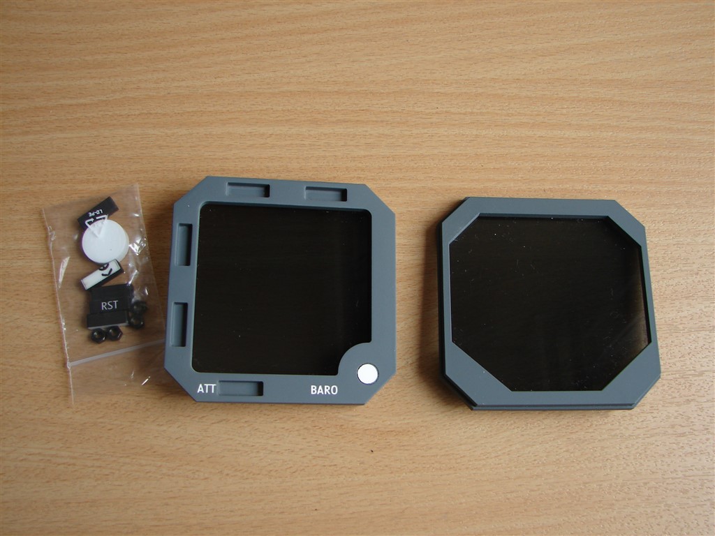
- Twoe to the RMI knoppen
The RMI buttons, I have met with ITS out of Peru. The rooms and nicely finished. The costs of transport, should you take it. You can have these buttons, it is possible to order it on a toggle switch to position (rotary encoder), or a dummy. In this implementation, they serve only as a dummy;


- The two TFT LCD display screens of 5 inches (5”).
These screens cover the openings in the MIP, and the openings in the bezels.
This TFT-LCD displays are made up from the set of the A/D Board (PCBA, controller cards, for example), the button board with the alignment, and connectors for VGA video input DC power input with 12V. The resolution is normally 640×480.
This is a 5” display screens, I have bought from the Chinese company Good Display. The windows are of good quality and the service from the company was excellent (Thanks to Ariel, Ma). The delivery is unbelievably fast ...;


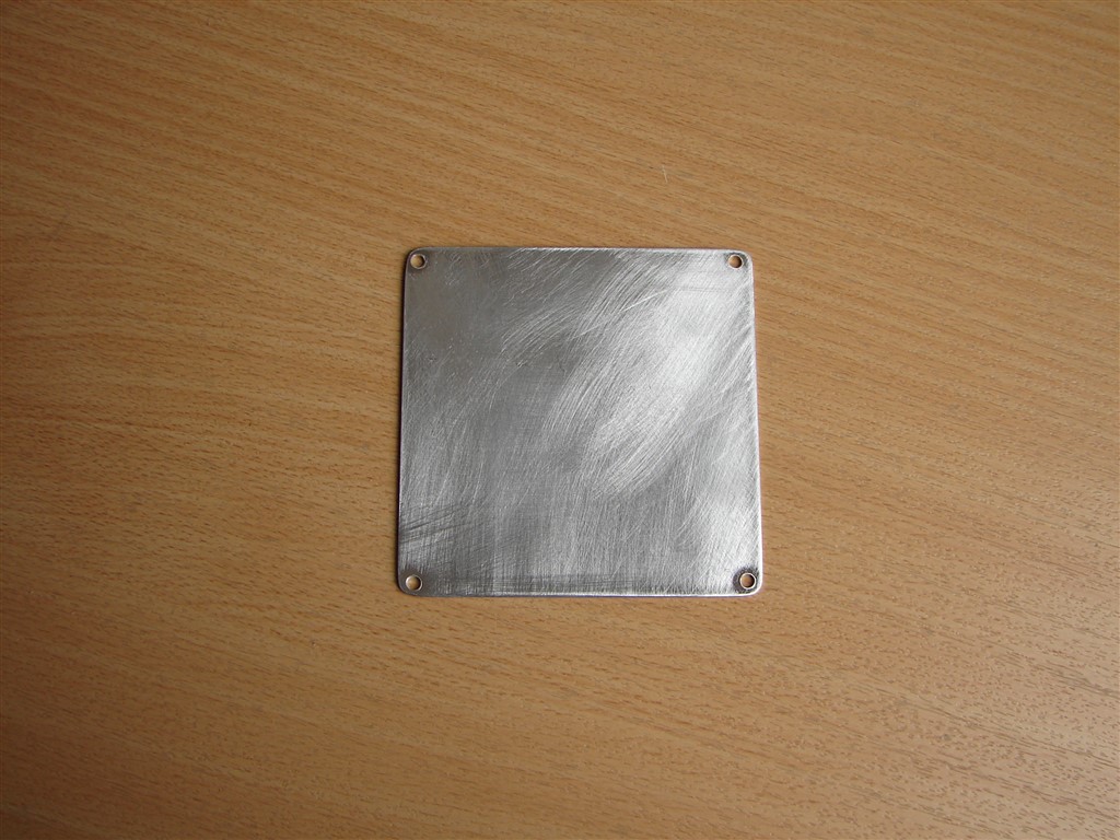
- Afdekplaatje
This cover is used to keep the gap to the top is not used, stby instr (analog attitude is a gauge cover.
The dimensions of this image correspond to the 4 holes that are already to be found in the MIP;
- Sdistribution or declare
This is a sticker with text on the reverse side of the cover. This decal (placard) I, like all of the other MIP decals, engraving;
- Two VGA extension cables
These are used to control the connection between the LCD DVI connector and VGA connector on the computer.
INSTALLATION
Bezels
- With the purchase of my FlyEngravity-MIP, it was this one, with all 3 bezels around the holes in the stand-by instruments.
That will have to be removed, as these bezels are not the same with the real one) ISFD and the RMI bezel. - With double-sided tape to the 3 and FlyEngravity - up bezels on the MIP, will be confirmed. They are relatively easy to remove by using a small-blade putty knife between the MIP and the bezel sticking out. Once that one is in-between is the rest of the insert will automatically release it.
Here, you have to proceed with caution in order to insert and MIPS, so as not to damage. - I then used the holes in the MIP is adapted to the opening of the new bezels. The holes in the MIP on the new bezelopeningen the square. So I have small pieces, need to saw off the aluminum MIP record over the visible parts of the behind the bezels are not to be seen. I just need to be removed, so that I may have the old bezels are still able to use with these bezels and the vents around it to cover or seal.
- The new bezels, I also have it on the rear side of the double-sided adhesive tape.
It is the art of making the bezels in the right place at the MIP to be the paste so that the holes in the MIP are fully covered. It also has to be level... - Of the ISFD-bezel is provided with ‘dummy buttons’. Those are just the openings is glued together.
- The RMI bezel I have fitted 2 of the RMI to use. One of them with a small bow and one with a thick arrow. These buttons are dummies and are just using some double sided tape on the bezel confirmed.


Color TFT-LCD display screens
- In order to the color TFT-LCD displayschermpjes to the places they need to be rotated . In the width there is not enough room on their side of the backside of the MIP just enough room. On both sides there is a thick and inches all over.
- First time I have been in the bottom panel of the MIP, with a small opening cut at the bottom and LCD screen ENABLES to them to begin. Otherwise, it remains a part of the bezel-opening of the ISFD. And that's not the point. Because of the bezelkaders quite thick and there is some play in and out of the 2 display screens nicely against each other without the edges of the display screens to be visible in both of the bezels.
- It is recommended that the A/D Board (PCBA controller card to connect the screen to the flat, brown-coloured strip.
First, on the AD/ Board sluitpinnetjes of the bevestingsblok be released by a reverse pulling. Then, the brown, the flat terminal strip on the white mounting block is pushed and then the vergrendelingspinnetjes back in the closed position, are pushed down.
Attention ! The brown of the flat strip must be on the right side of the bevestigingsblokje to be pushed in (see pictures) !
Be CAREFUL ! THE BROWN OF THE FLAT STRIP OF THE SCREEN IS VERY SENSITIVE, AND MAY BE IN A ROUGH MOTION, EASY TO DAMAGE OR TEAR !
IT MUST, THEREFORE, PARTICULAR CARE MUST BE TAKEN TO BE TREATED !
- Then, the A/D and D / a Board to the back side of the lcd screen to be rotated to where it is with double-sided adhesive tape is attached on the rear side of the display.
- In order to the color TFT-LCD display screens and to confirm, at the rear of the MIP to be on the edges of the front face of the brick, double-sided adhesive tape is applied.
The TFT LCD display screens to the back of the MIP press.
At the beginning of the time this happens, lightly, so that they will still be able to move it to the correct position, the edges of the screens, you may not see it on the front page of the MIP (bezelopeningen), and the display surface of the display screen, the full opening of the bezel cover, and they should be nice and straight and in a horizontal position.
Here are the screens carefully, and finally at the MIP press.


")


AANSLUITEN
- At first, all of the cables connected to it. That is, the power supply (12 V) and a VGA port.
With the power cable, I have the connector off, cut the wire, I just extended in the direction of block by an external pc power supply (12V). - The VGA cable is going to be a spare VGA port on one of the cockpit pc. In the lack of a VGA port, you can also make use of a The USB-VGA Display Adapter.
This is a USB Display Adapter, which is basically an external graphics card, where on the one side, a VGA port, and on the other side of the USB connector in to an available USB port on your computer.
In this unit, there is also an instruction manual and a CD with the necessary driver.
After the installation of the driver may be a computer screen via USB, and use it in 4 modes : Extended, Mirror, Primary Display Rotation.
You can, in Windows, by the way, the 4-to 6 adapters can be connected. You may not have known all of that, but it's working fine. The adapter(s) I have purchased from Rs.be (J5Create.comand they are available in 3 types : VGA, DVI, and HDMI.


CONFIGURATIE
- The configuration of the color TFT-LCD display screens consists of 3 parts : the first, in Windows, the LCD screen itself, and then in ProSim737.
- If the connections to the VGA are performed, and after a reboot, in the Windows of the 2 newcomers, all of them (display, screen).
- The first problem is that the screen is usually located on the wrong state. It is enough screen for Windows to move it to its current physical position.
(we will not have lessons out of it, it would be well-known subject matter should be the same).
The use of multiple screens, it's sometimes hard to tell which screen we have to do. Through the use of ‘Identifying’ or ‘Identification’ (in the View of your screens, change the") to get you back on the right track.
By the way, the resolution of these small TFT-LCD Dispays, it is 640 x 480.
A second problem is, when it is windows-based display image on the LCD screen will not be visible (for example, blue screen), and the reason is, on the one hand, that the screen does not have the correct input source has been reached. It is sufficient to press the "Source" button on the supplied LCD control panel.
On the other hand, it can also be a high-set display resolution in the Windows. This needs to be brought down to the 640 x 480. - A third problem is that the the image is tilted to the it is on his side. We have the screens, by the way is also on their side, just behind the MIP, set...
In Windows, the image will be tilted in the right direction. There is also free software, such as iRotate.
With the use of a USB Display Adapter, the image will also be rotated by the in-house software after you have installed the adapter driver. - When the screen is in place and the screen itself is correctly adjusted, the rest of us, only the one digital standby instrument is in the display. This is done by way of a Prosim Display Module.
By the standby instrument is connected to a separate Prosim Display Module is started. In the configuration of the module, Prosim will be chosen in the instrument, it needs to be.
In windowmode it is the scaled-down image in the window using the mouse, move it to the LCD screen. Then, the size of the image is adjusted according to the size of the TFT-display surface.
By the configuration of the Prosim Display Module may be one of the windowranden to make it disappear and you may not be in full-screen mode for a mode (for more information regarding the configuration of the Prosim Display Module, I would like to refer to as the Prosim manual).Every time, if you are in the Prosim Display Module to start up is the main instrument of the good, at the same location will appear.


Translated by Yandex.Translate and Global Translator