Circuit breaker panels
PARTS REAR CAPT SIDE
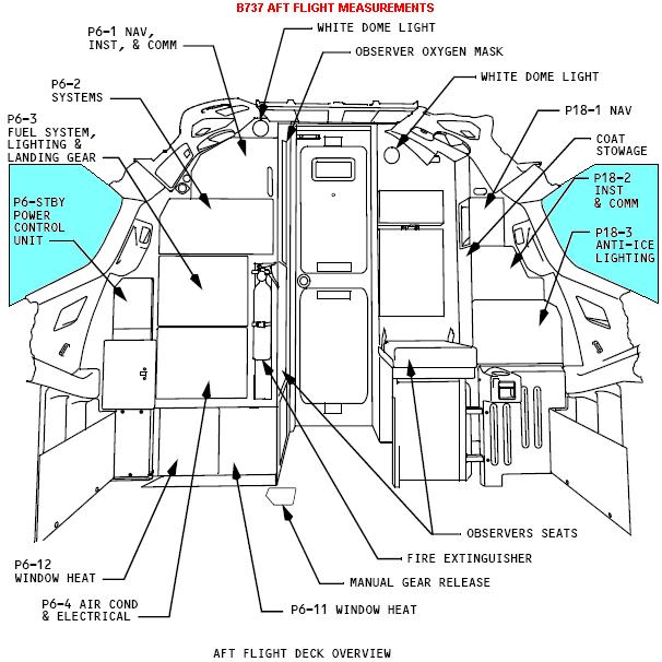
The back wall (back wall) of the Capt I is composed of following parts:
- Dome light with opbouwblokje back wall;
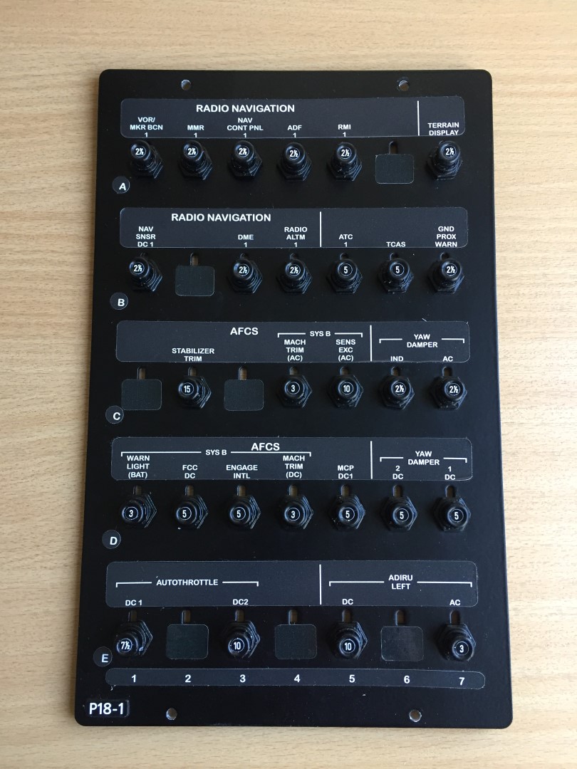
- Circuit breaker panel, P18-1 (Nav);
- Circuit breaker panel P18-2 (Inst & Comm);
- Circuit breaker panel, P18-3 (Anti-Ice, & Lighting);
- Head phone dummy panel;
- Development with housing for cup holder and ashtray;
- Cup holder and ashtray;
- Ad Grimes light;
- Flashlights with holder;
- Dummy ‘observer seat’ cushions, and frame pad holder and ‘safety belt’;
- Maphouder;
- Amp-stickers-CB";
- Decals with panelnummering and inscriptions;
- Circuit breaker button caps;
- Nis with upper rail window P2’;
- Ad " upper rail window P2’.
 DESCRIPTION
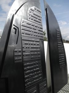
The ‘circuit breakers’ are the different electric fuses that are to be found in a B737. Each individual elektriciteitscircuit for any kind of purpose has its own fuse or ‘circuit breaker’. The total would rise to over 1100 pieces.
A ‘circuit breaker’ is normal operation if this key is pressed and when an electrical breakdown, jump back out. To some fuses faster one uses colored caps or rings out (‘chicken rings’).
A large number of these ‘circuit breaker’s are found on the walls behind the Capt and the FO. These ‘circuit breakers’ are arranged on separate panels, and this according to their common features. Each panel has its own specific number.
Naturally, in this homecockpit the ‘circuit breakers’ but dummies and serve only as a show element to the rear walls to fill with a realistic look ...
FLYBYCOCKPITS
The "circuit breaker" panels that are to be found in my homecockpit come from Flybycockpits (Portugal).
During my visit to the FSWeekend in Lelystad, the netherlands on Nov 01 2014 I've on the state of Flybycockpits a ready-made CB-panel seen. The CB panel was beautifully made and in detail finished. They have also all CB-panelsset in their product line (total 10 pieces).
I first toyed with the idea for the ‘circuit breakers’ panels themselves to tinker but after advice from some of the handymen I have, this was not done. It would be just as much true than with the purchase and the question is whether this DIY project could succeed ...
In total, the 10 panels of which 7 pieces for the FO side and 3 pieces for the Capt side. This number I have supplemented with additional panels that are not by Flybycockpits be delivered.
This extra homemade panels are:
- small headphone panel at the top on the Capt side;
- ‘latch’ panel at the bottom left of the FO-side;
- expansion of the panel, P6-STBY (Power Control Unit);
- panel with 2 power outlets, 115V AC and 28V DC on the FO side;
- Handles


These ‘Circuit breakers’-panels of Flybycockpits I've extended with a few additional attributes that are also found on the OEM versions, such as handles, decals with the numbering of the panels and decals with the number of amps per fuse.
P18-1 (Nav)
P18-2 (Inst & Comm)
")
")
P18-3 (Anti-Ice & Lighting)
")
")
Head Phone dummy panel
")
")
")
")
")
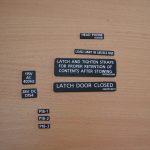
DECALS with panelnummering and inscriptions
The various CB-panels of Flybycockpits are not equipped with their specific paneelnummers. I have them so self-duplicate including the decals for the ‘Latch Door’, the door at the bottom left of the FO-wall.
DECALS Amp CB's
Each CB has its own amp amount on each CB state.
Someone from the cockpitbouw community had the opportunity to visit the real cockpit and with much time and patience does this guy have all the Amp numbers written down to use in his own cockpit. The list I got after a question about this on a forum ...
All Amp's I have in their type and number counted, and that make use of sticker or decal. Matter to them in the right size to make them fit in the middle circkelopening. Here and there, there will be one on the wrong place ...


")
Translated by Yandex.Translate and Global Translator