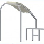
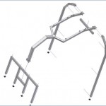
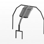
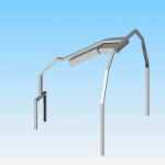
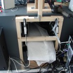
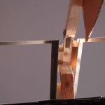
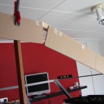
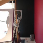
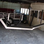
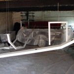
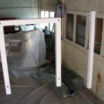
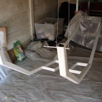
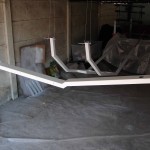
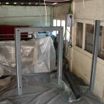
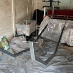
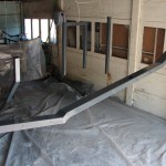
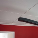
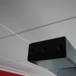
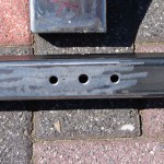
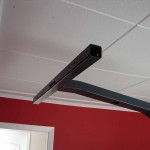
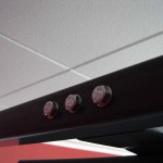
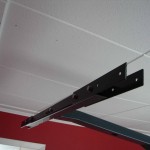
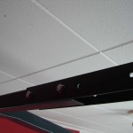
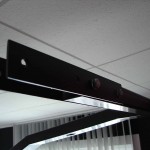
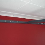
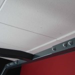
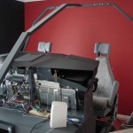
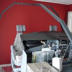
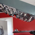
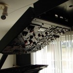
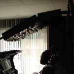
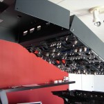
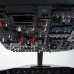
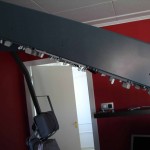
Frame overheads
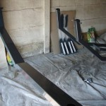
The crafting of this metal support frame for the overhead is also enhanced by a good knowledge of me Paul Cox. He has the welding for me and provided useful advice during the preparation of this construction. Thank you to Paul.
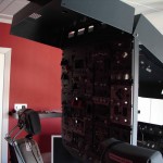
The construction of this metal frame was a work of long breath. To this construction there was lots of measuring and adaptation work.
There must be taken into consideration with various factors such as height, MIP, the correct angle of inclination for the both OVH's, the correct heights and distances between OVH and MIP. Simultaneously, I also need to construction where afterwards the B737-windows at the right place and height need to be mounted on this metal frame.
It all looks simple but it is not to be underestimated ...
- Which method to apply;
- Dimensions and measuring;
- Composition frame;
- Painting;
- Connections and installation;
- Confirmation overhead.
.
WHICH METHOD TO APPLY
In my research I examined what possibilities we have for placing the FWD and AFT Overhead.
Here, 3 methods are used :
- Fastening on/in a wooden or metal frame that against the ceiling of the cockpitkamer is made;
- Confirmation in a metal or wooden framework over the cockpit is built;
- Confirmation under a metal support beam over the cockpit is built.
Ceiling
A confirmation against the ceiling in the room where the cockpit is, I found, personally, a good solution for me. It seems the overhead is not part of the cockpit but is a part of the ceiling or cockpitkamer.
Also, when the cockpit of what must be moved, all of the ceiling removed and re-installed to a different place. A whole job so ... and the ceiling is seriously ‘maimed’.
In a small room, where the cockpit is enclosed by walls, a ceiling suspension less.
In a metal frame
This way of mounting is usually used. Everything is in metal (some in wood) with the OVH's in a wooden or metal frame to fit and with the bottom edge of the overhead equal walk to the bottom of the frame. When the wood is made the framework (frame) is usually a part of the cockpitshell. This for strength.
Under a metal bracket
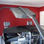
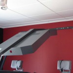
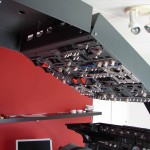
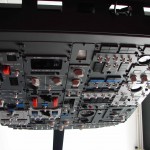
This system can be compared with the above way (in a box) but here are the OVH's not a framework but hang under a metal support arm.
I have this system seen only at FlyEngravity system and sell it as a finished product in aluminum.
.
I have to choose this system for its simplicity and the ability to OVH to be able to shift.
This support structure I have in metal, but not aluminum. Not only that aluminium is a suit more expensive, but mainly the special welding technology and equipment to come in handy. The use of iron pipes is heavier but the weight adds to the stability of the whole.
.
.
DIMENSIONS AND MEASURING
On the Internet have different dimensions. I have the dimensions held that to be found on the website of Markuspilot.com.
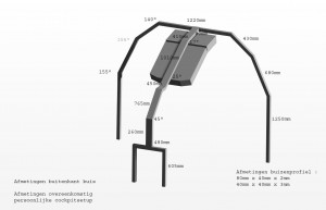
I started with all the draw out on graph paper. First, the MIP platform scale and then the support frame.
I have a few ‘goals’ or referentieafmetingen respected with the rest of the construction should follow in the further drawings.
These reference points are :
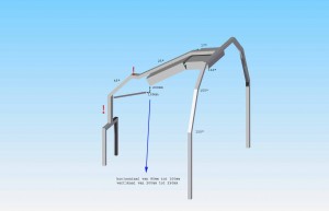
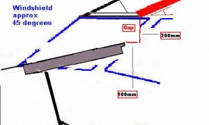
- Vertical distance of 200mm between the bottom of the OVH and the top edge glareshield;
- Horizontal distance of 100 mm between the bottom of the OVH and the top edge glareshield;
- Angle of inclination FWD OVH of 25°;
- Angle of inclination AFT OVH of 17°.
These ‘goals’ to obtain, it is necessary to ‘play’ with the length of tube + away glare of the vertical tube which is located behind the glareshield/MIP.
It is also a little bit to figure out what the correct length of the horizontal connector between the 45° (raamhoek)and 25°-tube (Fwd overheadhoek).
.
.
.
.
.
Further dimensions of the various components of this structure depends on which dimensions were used, for example, the height of the MIP, the width and depth of the MIP-frame, the dimensions and angle of the glareshield, the length of the cockpit, the width of the rear cockpit, etc.
The length of the tubing in the accompanying drawings are therefore only applicable to my cockpitsetup.
.
I also have to take into account consideration how afterwards, the B737-windows will be mounted against the middenstut of 45°, at what height the ‘windshield’ and the height and the width of the side windows, in their turn, must be connected with the rear upright legs of this metal frame.
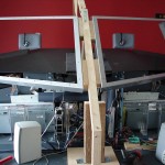
After the drawing, I have everything rough was reconstructed in wood and uitgepast. This is in order to see how everything in reality would have to come out and here and there, still some improvement should be applied.
Afterwards, can be started with the welding...
.
.
.
.
.
.
.
COMPOSITION FRAME
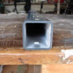
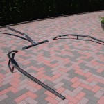
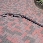
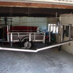
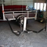
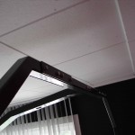
The frame is made of iron installation/meubelbuizen of 40mm x 40mm x 3mm and 80mm x 40mm x 2mm.
The tubes are purchased at Hardware Store Vanbeeck in Leopoldsburg.
All the tubes are first tentatively but on a few points welded together (spot welds). This gives the possibility to afterwards something to change or improve. Once everything is correct, everything is final welded and finished for painting.
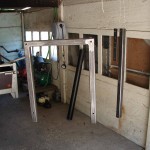
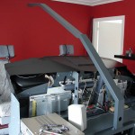
The whole metal structure is composed of 5 parts :
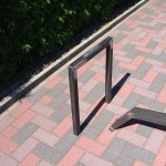
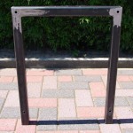
- Front steunvork
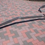
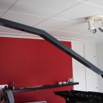
- Control arm
- Transverse steunbak
- 2 Upright steunbenen
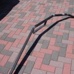
Front steunvork (40mm x 40mm x 3mm)
This front steunvork is located behind the MIP-frame and to the MIP frame.
The steunvork has a U-shape.
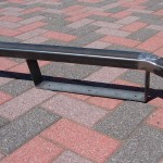
Control arm (80mm x 40mm x 2mm)
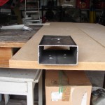
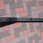
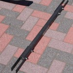
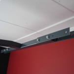
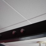
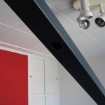
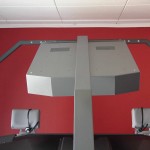
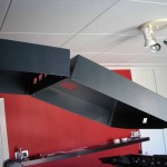
Under the control arm, the 2 overheads and confirmed. This control arm is on the front attached to the front steunvork and to the rear of a transverse strut which in turn is connected with 2 steunbenen.
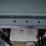
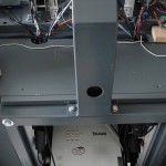
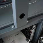
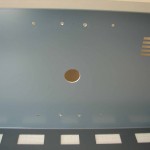
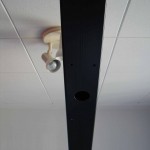
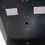
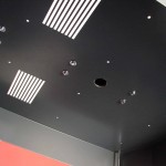
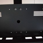
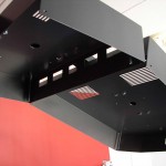
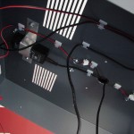
In this bracket are also 3 holes of 35 mm for the cable routing of the OVH's. One for the FWD OVH, one for the AFT OVH and one on the back of the MIP for the routing to the pc or power supply.
Strut (40mm x 40mm x 3mm)
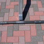
The strut makes the connection between the suspension arm and both steunbenen.
Steunbenen (40mm x 40mm x 3mm)
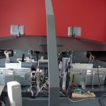
This 2 steunbenen stand behind the MIP (behind the seats) and are connected with the transverse strut.
They carry and support the suspension arm with strut to the back of the cockpit.
On this steunbenen are also brackets welded to the B737-side to confirm.
.
.
.
.
.
.
.
PAINTING
The painting of the metal frame is done in 4 parts : 2 x with a primer and 2 x with a coat of paint.
First, the metal pipes is degreased with a ontvettingsproduct and after that sand.
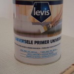
The primer that I used is a universiële primer that is also used in the MIP frame. This is suitable for both wood, metal and PVC.
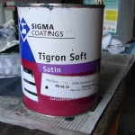
The coating is a scratch-resistant soft-zijdeglanslak of Sigma (Tigron Soft Satin) with as color code ACC R6.06.30 (or RAL 7011).
Between each paint job is all, lightly sand with fine sandpaper with fine grit. This for a better adhesion of the paint.
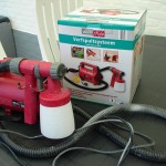
The application I have now not done with brush and roller but with a spraying equipment. Not as impressive as used in a spray booth for cars, but a do-it-yourself home and garden convenience device that I purchased at Aldi.
In the beginning it's a little bit of getting used to and practice the spraying technique under the knee got. It is important that the correct viscosity of the paint to determine and also after each spuitbeurt it is necessary thoroughly to clean.
CONNECTIONS AND MOUNTING
To this frame, in other hand, there are 5 connections, or links :
- Connection between steunvork and MIP-frame;
- Connection between front steunvork and support arm;
- Connection between the suspension arm and the transverse strut;
- Connection between the transverse strut and upright steunbenen;
- Connection between the upright steunbenen and the B737-side windows.
The front steunvork is attached to the back of the wooden MIP frame with 4 bolts of 10 mm thickness. This steunvork rest with his 2 legs on the cockpitplatform.
To the floor of the cockpitplatform not to damage there rubber feet in the bottom of the upright legs is placed.
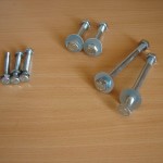
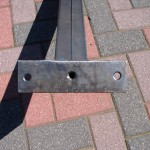
The connection between the steunvork and the support arm happens with 3 bolts: 8 mm thickness by a fixing plate that is on the end of the support arm is welded. The middle bolt is attached from the bottom to the top by the front steunvork and then tightened in the control arm (tapdraad).
The outer bolts go straight through the bevestigingplaatje of the suspension arm and front steunvork and tightened with a nut with a bolt.
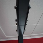
The link between the suspension arm and the transverse strut happens with three bolts of 8 mm thickness. They go all 3 by the transverse support beam and tightened to the tail end of the 80-mm suspension arm (tapdraad).
The link between the transverse strut and an upright steunbenen happens with 2 rectangular koppelingsplaatjes. The transverse strut is against the horizontal section of the upright steunbeen and then anchors on both sides and a koppelingsplaatje to confirm with 4 bolts of 8 mm thickness. 2 bolts by the transverse strut and 2 bolts through the horizontal part of the upright steunbeen.
To the floor of the room not to damage it rubber feet in the bottom of the upright steunbenen placed.
Later the B737-windows to connect with the upright steunbenen I have to both legs, a bracket welding. This raambeugel cross 140 mm out to the front and has the same height as the rear edge of the rear side windows. The windows are against the bracket, screwed with 3 bolts of 6 mm thickness. By this connection, the windows firmly and is the metal frame, more stable.
CONFIRMATION OVERHEADS
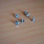
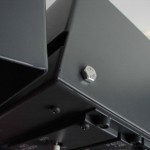
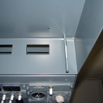
For the confirmation of the coverboxen of the overheads I have sleeve used that one normally use in the mounting of body panels of a car. These sleeve are 6 mm thick and that I have purchased from Fabory in Lommel, belgium.
This sleeve you can also buy them at any shop of body parts.
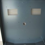
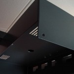
At first I was in the coverbox of the FWD Overhead 8 holes drilled 4.5 mm thick, and then paced to the support beam where I reuse the same holes 4.5 mm have drilled.
It's just the coverbox against the control arm bolts with the sleeve.
Afterwards, you can still use this sleeve to loosen and then back to confirm. The confirmation remains strong.
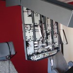
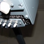
Then, it is simply the overhead frame with subpanels and buttons on the coverbox to screws. This link is done with 2 bolts of 6 mm thick to the back of the coverbox with the overhead frame completely to the bottom may be tilted.
For closing, the front is just anchored with 2 bolts of 4 mm thickness and this in the provided space (Index to lock). This coupling is done with a afstandspen with female thread in the coverbox on both sides is screwed.
Translated by Yandex.Translate and Global Translator
