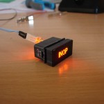
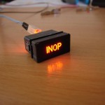
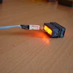
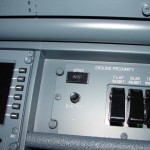
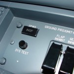
Assembly annunciator with leds
The F/O side of the Lower Dimming Panels lacked the annunciator ‘ON INOP’.
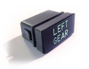
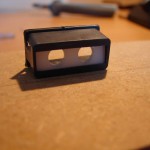
An annunciator or warning light is composed of a ‘annunciator holder with 1 or 2 leds.
The annunciator holder that I use comes from FlyEngravity.
.
.
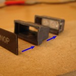
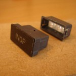
This holder is composed of 4 parts :
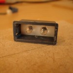
- Ledhouder containing 1 or 2 leds are placed;
- Holder in which the ledhouder that in the front of the aluminum backpanel’ is pushed;
- Holder which, in turn, in its entirety, in the ‘backpanel’-holder is pressed;
- Name-plate (legend).
.
The various holders are provided with tabs that settles in the back of the panel to the subpanel and also when the different holders in each other to be pushed.
.
.
.
.
.
.
.
PLACEMENT OF THE LEDS
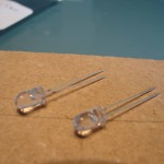
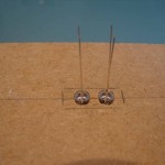
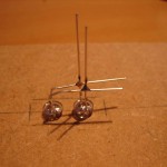
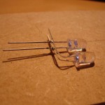
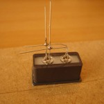
The two leds I have are parallel to each other soldered. I did this with a small jig in wood (tip René Hoep) so that the leds at the same distance as provided for in the white ledhouder of the annunciator holder. This template also eases the soldering.
.
.
.
.
.
.
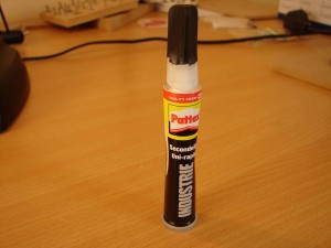
First is the white ledhouder in the backpanel-holder printed. Then, the soldered leds at the rear of in the ledhouder placed. Both leds are glued with the contents. With a glue gun, also, but this glue is rather on the thick side and dries very quickly. The contents is thinner and finer to be made. You also have some more ‘play’ in time.
.
.
.
.
.
.
WIRING AND CONNECTORS
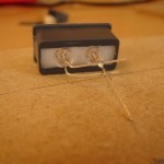
Afterwards, the wires to the leds and this by possibly making use of connectors. You have two sides from which you can choose where the cables need to come out. From underneath, or sideways. This depends on how much space you have on the back.
You can have the wires directly soldered on the leds but I have opted for the use of connectors. It has then afterwards the possibility of everything.
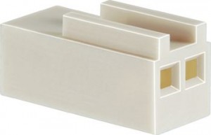
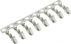
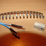
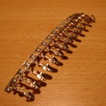
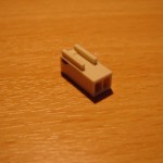
These connectors are composed of an empty 2-pin housing (RM2,54 mm) and a krimpcontact in the empty case, slide (tip René Hoep). These connectors are available from Conrad.be (nl) under the numbers 734021 and 733884.
.
.
.
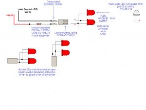
Here is a drawing of René Hoep, where he neatly explained how everything should be connected with each other.
.
As shown in the drawing is mentioned, it is necessary to use resistors for the leds optimally to burn. Without a resistor is a led a short life, and will immediately burn out. Therefore, this resistance to the flow of current is limited. Which resistance also depends which led you used.
*** Weerstandcalculator ***
As a test I have for these leds, a resistor is used from 1/4 Watt 120 Ohm.
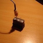
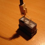
If the wires are connected to the leds (with a resistor!), do we have a test by the wires connecting it to a pcvoeding 5 Volt (red wire) and GND (black wire).
In the cockpit I have this annunciator is not connected directly to a resistor, but made use of the Pokeys Led Extension board. The explanation of the use of the Led Extension board is also to be found on this website.
.
.
.
.
.
.
.
PLACEMENT OF THE PANELS
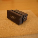
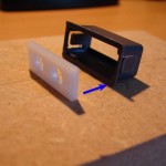
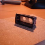
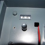
In the planned opening of the aluminum backpanel’ (Lower Dimming Panel) first, the holder with the leds pushed. Afterwards, the holder with a name plate in the ledhouder printed.
.
.
.
.
.
.
.
.
ANY LEDS
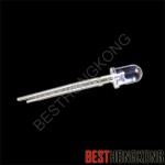
The leds with amber color I ordered from BestHongKong. Also the address where FlyEngravity and the Aviation Mega-Store they. If I use the forums, see are the same type of leds used in their MIPS and Overheads.
Article SKU no Amber led : BUAC333W20BA08
Specifications :
- Ultra Bright
- 5 mm
- View angle : 20°
- Clear 6000 mcd
- DC forward voltage : VF (IF=20 mA) 2.0 V-2.3 V Typ, 2.5 VMax
- DC reverse current : IR (VR=5V) 100uA
- Intensity : (IF=20mA) BA08 : 4000-6000 mcd
- Wavelength : Wd (IF=20mA) 600-610nm
Translated by Yandex.Translate and Global Translator
