Backlight Controller
BACKLIGHT CONTROLLER
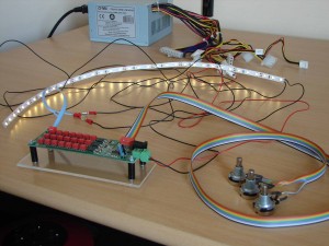 With the purchase of the Lower subpanels, I have at FlyEngravity also a backlight controller bought this for the lighting in the cockpit to close, and to regulate (dim). Normally, this controller is mainly used for the wiring and the dimming of the backlighting of the different MIP subpanels.
The ICS MIP has a separate power supply and can therefore not be connected to these backlight controller. In this cockpit are the subpanels of the ICS MIP directly connected to a multiple switch of the Lower Panels (MAIN PANEL).
The backlighting of the Lower subpanels are also directly to closed on the same multi-switch of the Lower Panels (MAIN PANEL)
The backlight controller adjusts currently the lighting of :
- AFDS Flood (right before and above the MCP)
- Background (indirect illumination in the glarewings and under the glareshield – MCP)
- Backlight standby instruments –Skirt –Yaw Damper – Brake Pressure
.
DESCRIPTION
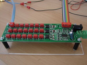
The backlight controller is composed of 3 channels and each channel can be separately dimmed.
- The first channel I used for the adjusting of the AFDS FLOOD (MCP);
- The second channel is to adjust the BACKGROUND lighting (MIP glarewings and bottom of the glareshield);
- The third channel is used for the dimming of the backlight instruments.
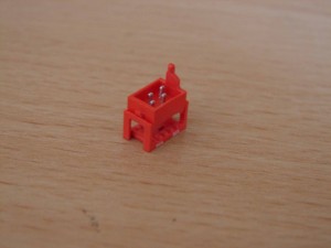
Each channel is composed of 7 red connectors. Per connector can be something suited for dimming.
When one is so single-channel afregeld will this apply to all connectors of that channel.
In this backlight controller, there is also a 4-wire flat cable and a few connectors.
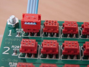
One end of this flat cable with a nijptang in the connector pressed. Then the connector mounted on the backlight controller.
On the other side of the 4-wire cable the insulation is removed. In the middle is this cable gesplist so that one 2-pair cable, each 12v.
One pair I have used to connect (e.g. on a Led strip). The other 12v cable I have left untouched, and a little shorter cut.
The 2 outer wires are the positive (+) and the 2 inner wires are the negative (-).
So the 4-wire flat cable is as follows : + – – +
It is recommended that the 4-wire flat cable, only one connection per red connector, i.e. one panel or one led.
The other pair of the 4-wire flat cable is not used and insulated against any short circuits.
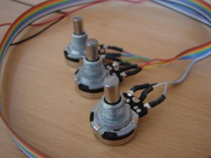
Further we find in this kit a 10-wire flat cable with at one end a connector that the backlight controller is able to prick. On the other side of the cable are three dip switches (rotary switches) in the Lower panels to build.
The backlight controller may be connected to a 12V adapter or a power supply of a pc.
Yellow = 12v (+)
Black= Gnd (-)
Translated by Yandex.Translate and Global Translator
