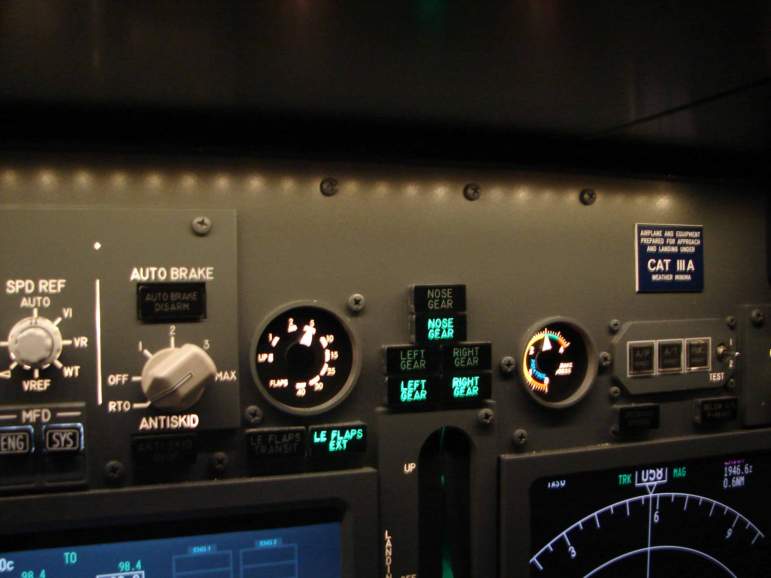
Wing / Brake Pressure / Yaw Damper gauges
 DESCRIPTION:
Skirt
The flaps increase the liftvermogen of the wing will reduce the stall speed during takeoff, low speed maneuvering and landing.
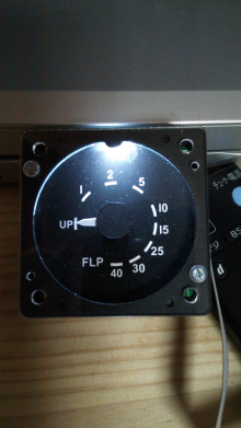
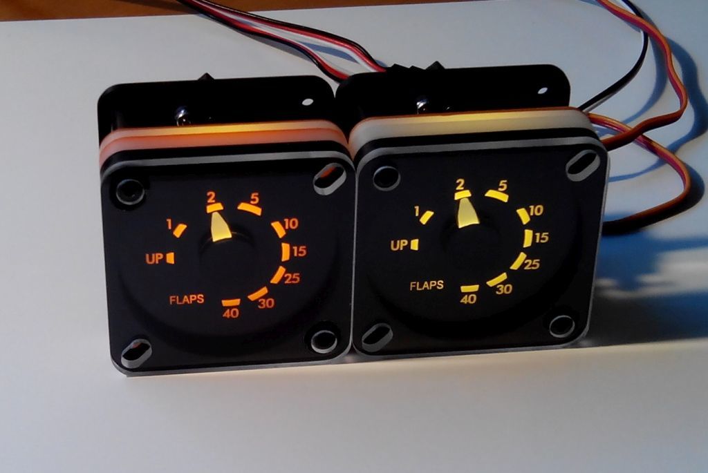
In accordance with the arrangement of the Flaps Liver on the right side of the throttle quadrant, this position will be displayed on the Flaps Position Indicator". These "Flaps Position Indicator" or the Flaps gauge is in the middle of the MIP top right corner of the Upper Eicas’. The Flaps Position Indicator the Indicator is divided into 9 levels : UP to-1-2-5-10-15-25-30-40.
The various positions are indicated by 2 of the needles (arrows). One of them is for the left-wing-TO-Wing (Trailing Edge Flaps), and one for the right-wing-TO-Wing. In addition, they can also be an indication of whether there is asymitrie or a skew is generated between both of them.
Brake Pressure
The brakes of a Boeing 737 is done using a hydraulic press. The normal brake system is powered by hydraulic system B. The back-up or alternate brake system is provided by the hydraulic system A.
If system B fails or the pressure is too low, will make the system A will automatically take the necessary hydraulic pressure supply to the alternate brake system.
The pressure of the braking system is shown using the Hydraulic Brake Pressure Indicator’. It is located at the top right of the ‘Gear lever’. The scale of this gauge is divided up into 1-2-3-4. In each figure, the PRESSURE pressure x 1000 (the pressure exerted by a one pound force on a one square inch).
The Brake Pressure gauge shows the pressure in the Brake Accumulator:
– Pressure : 3000 psi;
– Maximum pressure : 3500 psi;
Normal oplaaddruk : up to 1000 psi.
Yaw Damper
A Yaw Damper means is actually in which the unwanted movements of the rudder shaft, away (‘character’, and ‘yawing’ oscillations, or more commonly known as the " Dutch Roll) .
Some of the aircraft the shorter the distance between the tail and the CG, the greater will be the effect of it is to get a sort of swinging motion at the height of some of the inputs, and sometimes also at lower altitudes.
For the passengers in the back sit, and the "Yaw Damper" is to be the best I have ever stayed at, when you're on the left, to the right, gone up and down ...
The yaw damper gauge shows whether the aircraft is very stable in flight. The white dash should be in the middle to continue.
CUSTOM SIM PARTS
In general
In the world of the cockpitbouw, we can say that Flight Illusion some of the market leader in the supply of meters, clocks, or gauges. The company has a large product range available to everyone, however, you need to in able to find.
The gauges of your choice, are made with quality materials and fine workmanship. The power of the FI gauges is done with the steppermotoren.
A couple of points that have the FI gauges are quite expensive, it is not always easy to configure, and it is not a realistic backlighting feature.
There is a small led on the front panel the front panel which the front panel is lit, some of the FI gauges are equipped with a FLUORESCENT-type white led, Ice white, or keukenlicht). It is, therefore, not a matter of ‘backlighting’...
Incidentally, using the Prosim737 forum and I ended up with Custom Sim Parts. This company makes gauges, but for the time being, to a limited extent. At the time of this writing, only the Boeing 737 MIP gauges, such as Flaps and Brake Pressure, and all of the Boeing 737 Overhead gauges.
![]()
What are the gauges of the Custom Sim Parts if of interest to you :
- Cheap
- All of the gauges can be custom-made to be made in accordance with the requirements of the customer.
- The backlighting is a very realistic and beautiful;
- Very easy to install and simple to configure;
- Can be used with Pokeys Years Led extension board and Prosim737 for a real-life backlight control.
Size
From the first contact with the Custom Sim Parts will be prompted for the size (diameter) of the gauge holes on the MIP or on the Overhead. This, together with the size among the different boutgaatjes that the gauge needs to be fixed.
Reducing the size even more, the paint it can also be a few close-up photos of the front and back of the MIP or Overhead it will add.
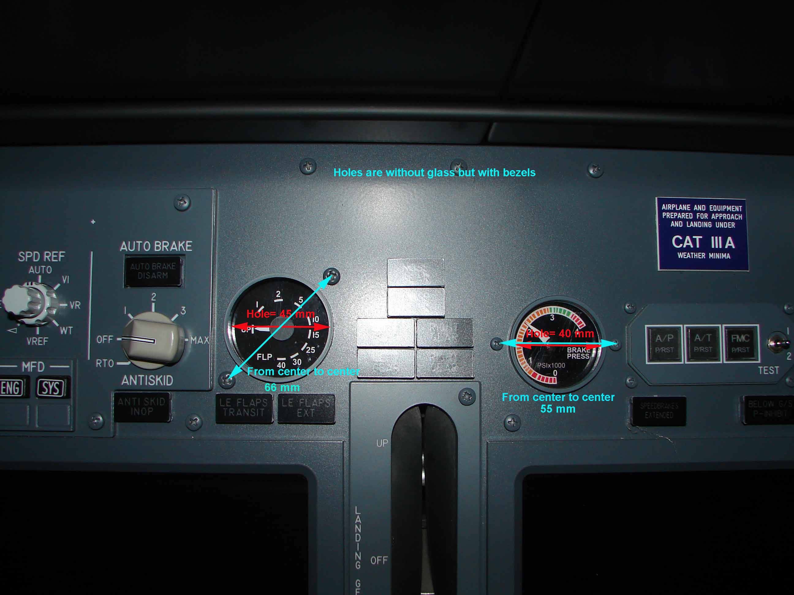
(The gauges in the picture are dummy)
In critical areas where there is little or no space due to the presence of an on / off switch, or a circuit board, then you can always try to find a solution, for example, the gauge may be smaller or in a different form, to be delivered (e.g., diamond-shaped).
Of course we'll send one of the Custom Sim-Parts is a drawing showing the proposed dimensions for clearance.
FlyEngravity MIP - Gauge dimensions
If it's the gauge holes on the MIP and OVH are equipped with a glass, the CSP gauges and pull out the glass in front of it.
Management
The control signal of the gauges is done using a standard digital servos and a Pololu Servo Controller. This is available in 2 versions :
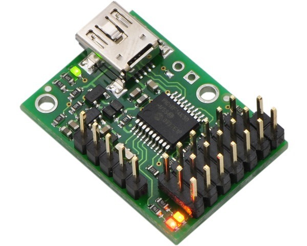
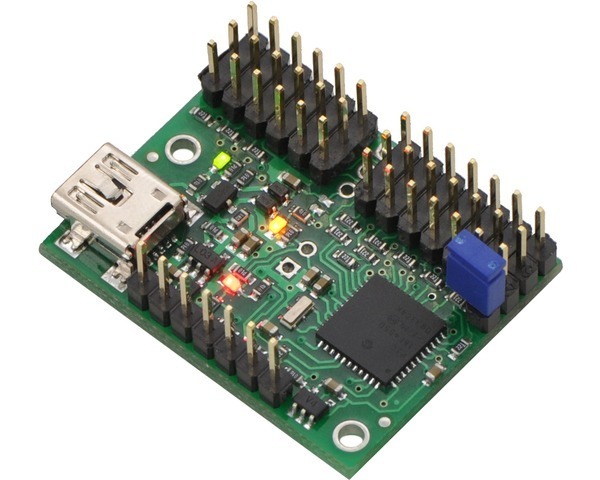
The 6-Channel version is most commonly used for the MIPS, and the 12 Channel for the government.
The 12-Channel controller, it may be necessary MIP+OVH also work to connect, but the distance from OVH>MIP for the Flaps and Brake Pressure gauge can be an obstacle ...
Therefore, it is much easier for the MIP and OVH separate controller.
The remaining free ports of the controller can be used for digital Inputs/Outputs. Unfortunately, it is the Prosim737 is not compatible with the Input/Output channels. Just as the Servo channel will be recognized by Prosim737. This is a bit of a shame ...
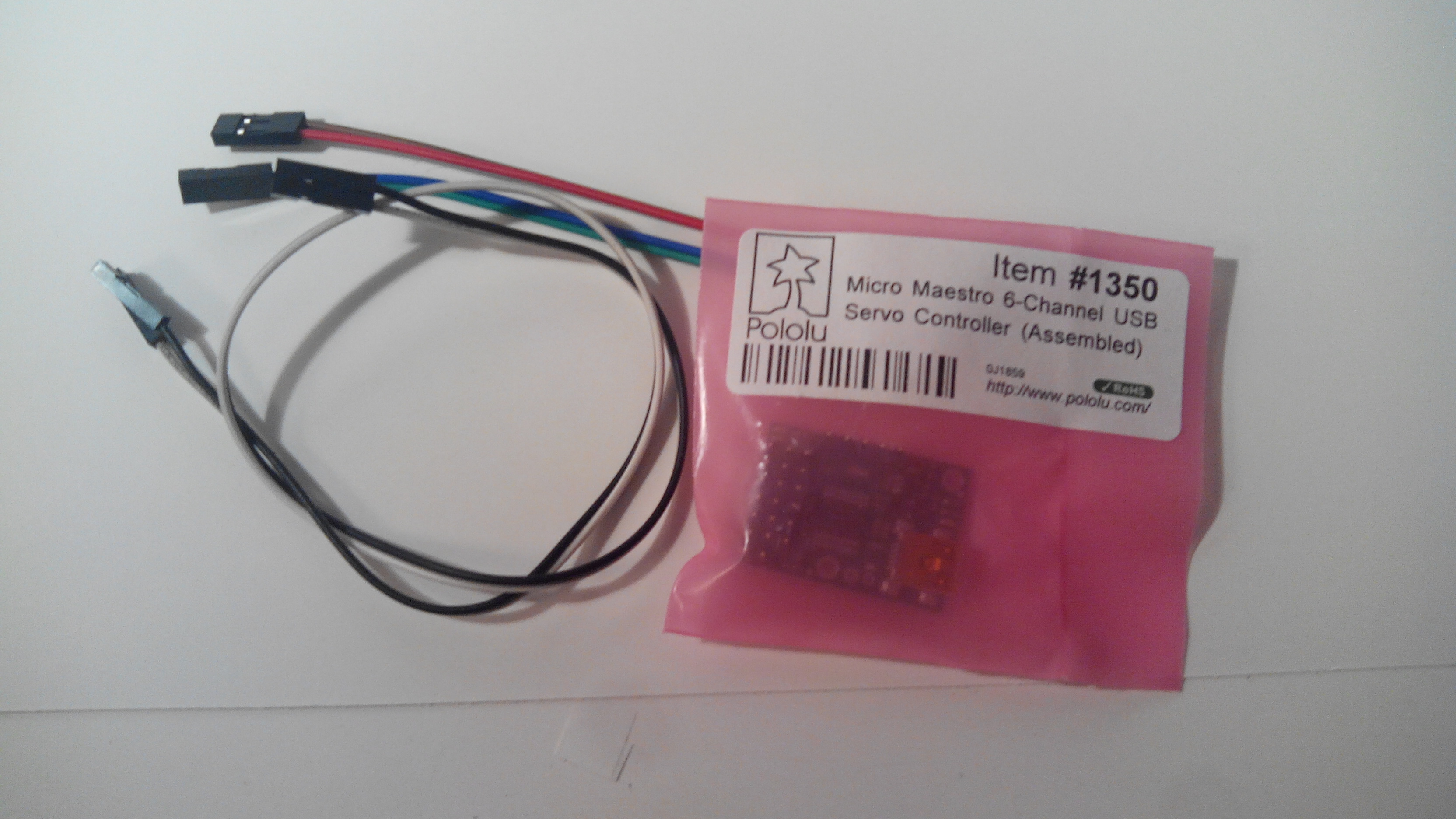
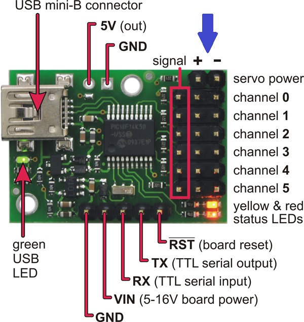
This Pololu Servo Controllers, are completely pre-assembled. They are very small (30 mm x 20 mm) and they are so easy to work with behind the Mip, or at OVH.
Backlighting
The backlighting is done through leds behind the front panel is to be installed. The color of the backlight can be, and is, therefore, optional.
The default is ‘warm white’. It is also possible to opt for Amber in color.
My FlyEngravity MIP and OVH panels are all fitted with a fridge, and white backlighting. For this reason, the backlighting of the MIP and OVH gauges can also be fitted with a warm white color.
The lighting level can be driven by the Pololu-controller port using the included splitter cable.
It is also possible for the backlighting to focus on more realistic solutions (see dedicated section).
SERVO MOTORS VS STEPPER MOTORS
Gauges can be powered by servo or steppermotoren. Both methods have their own advantages and disadvantages.
http://www.arrickrobotics.com/motors.html
The gauges of the Custom Sim Parts are equipped with the digital RC servo. Why is that?
- Servos are much easier to implement than a stepper motor, and is much cheaper;
- They can be connected to any standard servo controller and some of the gauges are universal or widely applicable;and
- The Servo-controllers are inexpensive, and there is a lot of choice;
- In the market, it is not easy to find a combination of a steppermotor controller for a similar price as a in the servo controller.
Spare PARTS
What are the components we need in order for the CSP-gauges to be installed :
- CSP gauges;
- Pololu servo controller (The 6 Ch And 12 Ch, or both);
- USB cableUSB 2.0 Cable – A-Male to Mini-B 1.8 metres) ;
- Connectors + cables to establish the link between the servo controller and the gauge(s).
- Use an old Pc power supply for 5V;
- Bolts and nuts M4;
- The Drivers for the Pololu servo Controller.
All of the cables and connectors should be free of charge included in the delivery (except for the USB cable). 🙂
INSTALLATION AND WIRING FOR THE POLOLU SERVO CONTROLLER
1. To install the Pololu driver with the "Maestro Control Center":
Maestro Servo Controller Windows Drivers and Software (release 130422) (5MB zip file)
This ZIP-archive contains the installation files for the Pololu Controller using the Maestro Control Center, the Maestro Command-Line utility for the Pololu Maestro Servo Controller and driver for microsoft Windows.
2. To connect with the Pololu Servo Controller with the USB cable:
The Pololu Servo Controller should be connected to the the pc where Prosim737 it is installed on. This is done with a USB to Mini cable
(USB-A male <=>USB B male 5-pin (1.8 m).
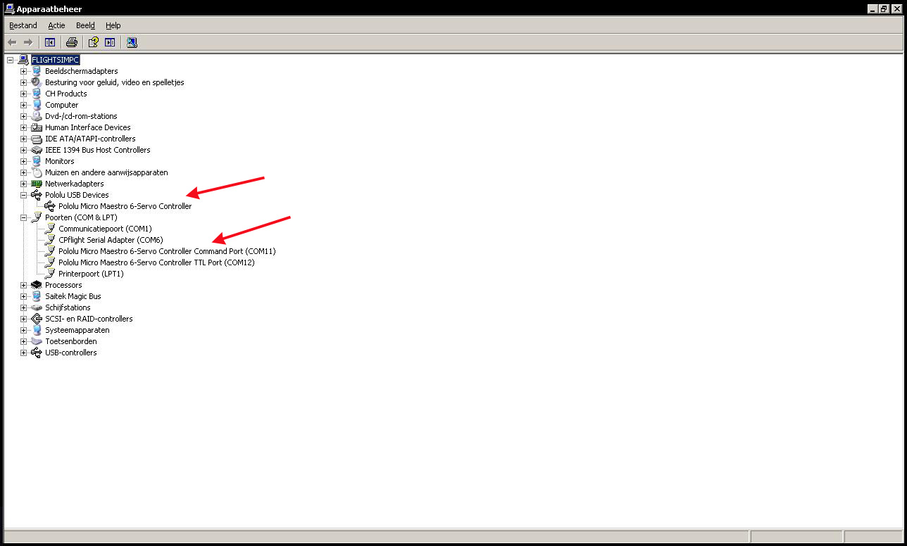
3. Make sure that in "device Manager" tab in the Pololu USB Controller is installed:
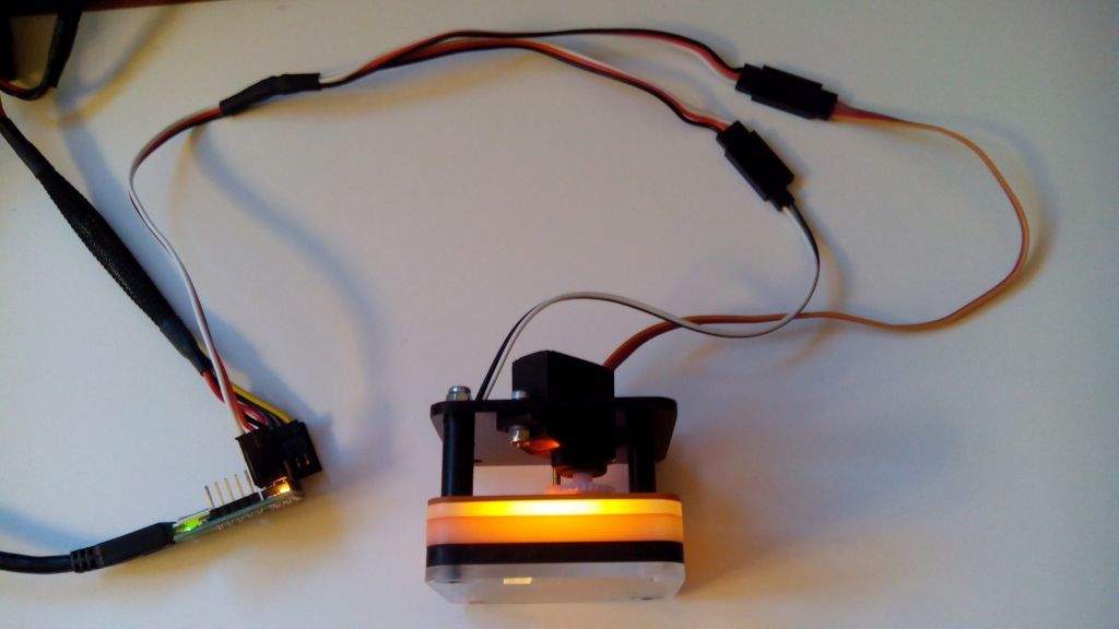
4. It connects to the servo in the gauge and the backlighting, with controller:
The gauge is made up of 2 small books cables : the cables that come with the servo, and set the lighting level.
Both of them are with a splitter cable connected to the controller.
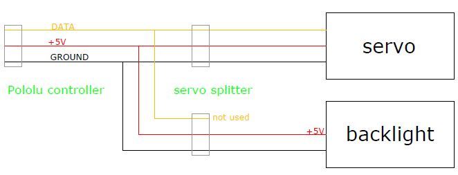
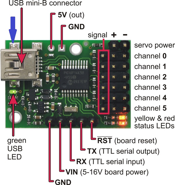
The flat-jacks, or connectors to the servo's, including 3 threaded ports : one (1) white is for the signal, and the other two to the + (red) and – (black).

5. The controller will connect to the 5V-power-supply
The 5V power supply, one can get an old pc power supply. Usually this is a homecockpit is already equipped with a ‘Power Supply’container, and be able to do all these in some way in your life. The flat plug is for the controller only has 2 terminals, + and – . Third, it is not in use.
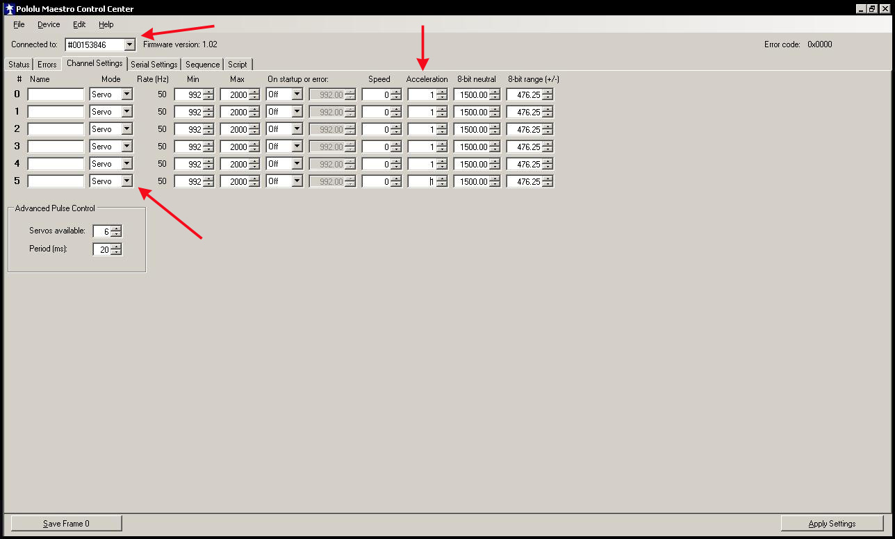
THE CONFIGURATION OF THE POLOLU SERVO CONTROLLER WITH THE MAESTRO CONTROL CENTER.
6. Open Maestro Control Center and make sure that the controller is connected to ("Connected to" followed by the appropriate number).
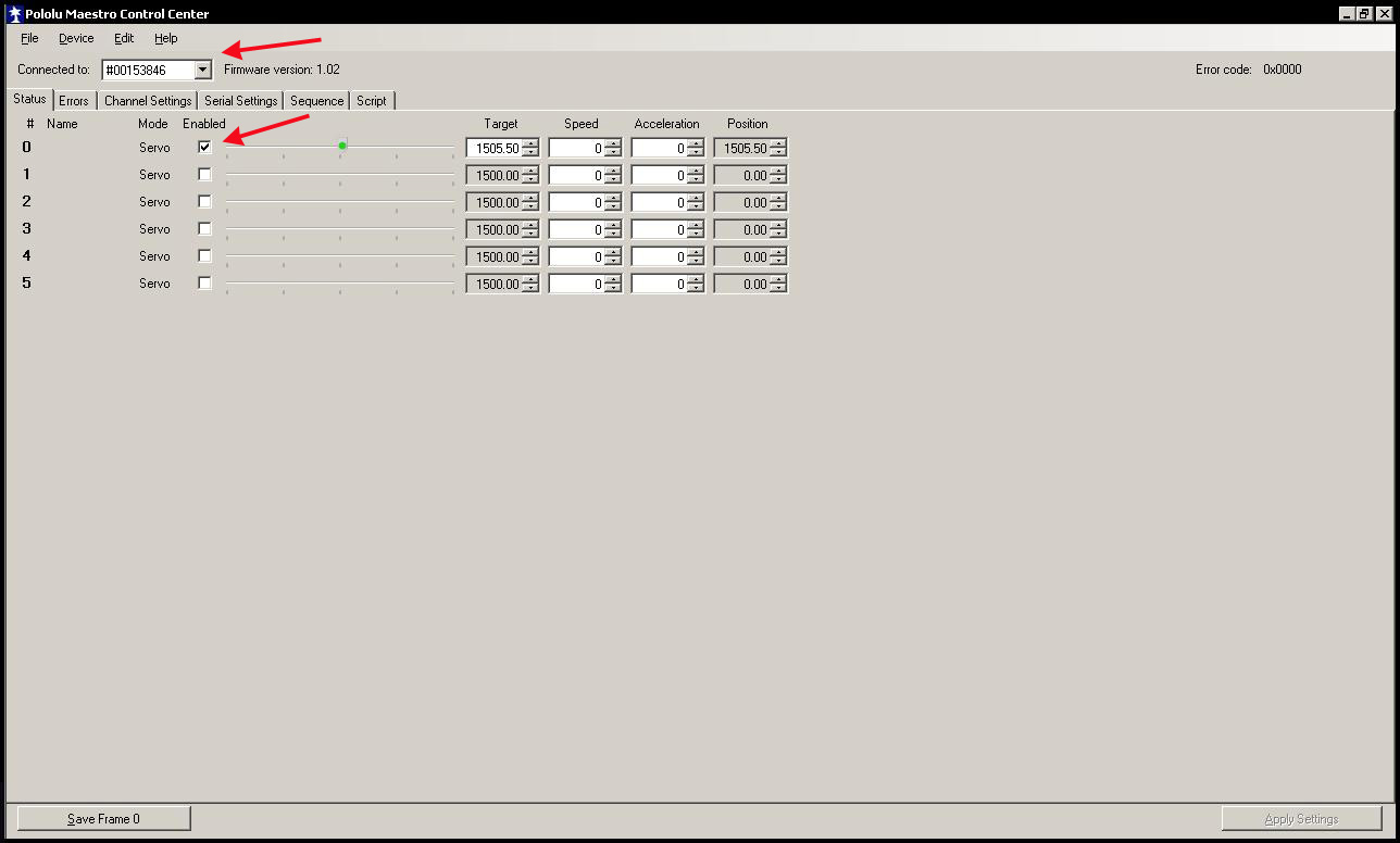
7. Switch to the allocated channels (0-1-2-3-4-5) by placing a tick in the check box (enabled by default);
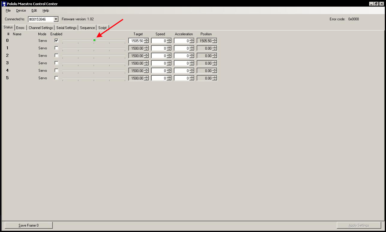
8. Make sure to test it with the servo (by moving the sliders. The dial of the gauge, together with the slider for movement;
9. Please go to the "Channel Settings" tab;
10. If all of the channel options on One (this is required in order for the needles or pointers on the gauges easier to move around);
11. Click on the "Apply Settings" and exit the program.
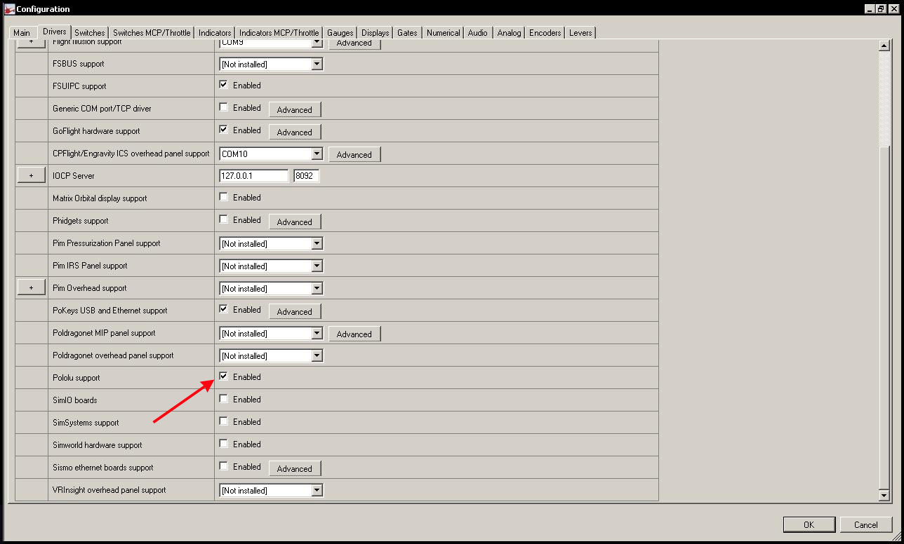
THE CONFIGURATION OF THE PROSIM737
12. Start Prosim737;
13. Open The Configuration/Drivers Are;
14. To Enable Pololu support by checking a box;
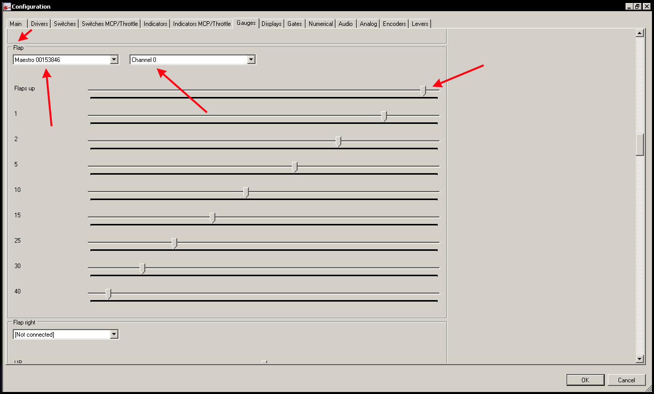
15. Go to the Gauges tab;
16. Scroll down to the bottom of the right gauge;
17. Choose the right Maestro is the Controller in the drop-down list;
18. Select the channel to which the gauge is to be connected;
19. To configure the slider to the correct setting on the gauge, and then press the OK button;
20. - Open your Flight Simulator and do the test, Make necessary corrections, if need be.

VIDEO
THE LIGHTING LEVEL TO BE REALISTIC ENABLE
As for the connections of the lighting level above, and you plug the power cord into the wall outlet, then lit up with the backlighting of all the gauges. Not a true ‘Cold and Dark’condition, and therefore it is not realistic to ...
The lighting level according to the Boeing manuals will only be allowed in the cockpit under an AC power condition. Note: this is the set-up of the Ground Power, the APU, or in the case of active Arrays.
So how can we simulate it using the CSP gauges, and what are the possibilities?
- To connect with the backlighting for the gauges directly to 5V and a switch to switch between them. Once in the cockpit, it's switching to AC power, turn on the power switch is on;
- Associated with the switch is the Ground Power (via a low-voltage high – resistance reed relay with a separate circuit from the 5V or 12V). If the switch is the Ground Power, then the relay is for On/Off and the lighting level to switch to.
But it is possible that only the "Ground Power" ... - A card with digital Outputs and is compatible with Prosim737. In the Prosim737 configuration, a bridge is used;
http://www.phidgets.com/products.php?category=9&product_id=1014_2 - The use of Output-channels available in the Pololu Maestro Controller and attach it to a Bridge in the Prosim737 as described above).
Unfortunately, this is not possible, as Prosim737 is not compatible with the In-and Output channels of the Pololu Controller. At the time of this writing, Prosim737, only to be used with the Pololu servo channels; - The use of Pokeys Controller and a corresponding Led extension board. In the Prosim737 configuration, a bridge is used.
Since I was one of the first users of the Pokeys card and the Led extension board, I have also examined, along with the Custom Sim Parts and FlightSimParts.union (The).
After a lot of testing, I found this to be the correct, easiest, and cheapest, solution is to set the lighting level to be realistic to drive.
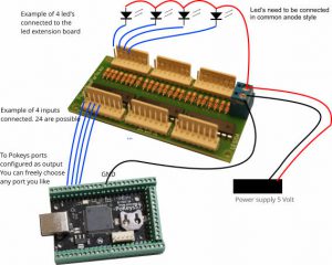
The control of the lighting level on the Pokeys micro-Controller " Led extension board and Prosim737
Here follows a step by step approach to the Pokeys, and the led extension board and the Prosim737 configure it so that the backlighting of the gauges starts to light up when turning on the AC power:
- Unplug the crimps from the backlighting separately from the single pack (of the Servo, and lighting level). The 2 wires (+ and -) of the backlight and lighting is now a separate;
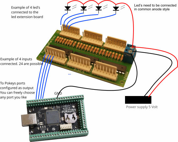
- Connect the red (+) wire of the lighting level in parallel to each other and to connect the latter to the common (+) side of the Led extension board;
- Connect the black (-) wires from the lighting level to run in parallel with each other, and to connect the latter to a single port on the Ledaansluitingen on the Led extension board.
(The Led extension board is divided into 2 parts : one part is where the leds are to be connected, and the other half is where the connection to the Pokeyskaart).
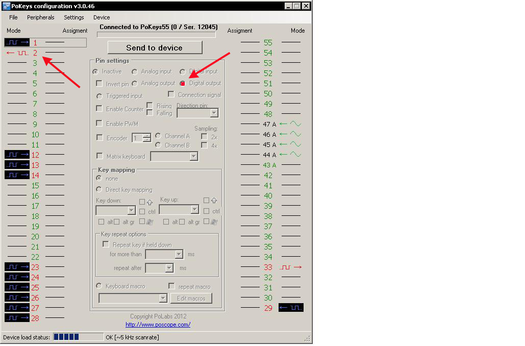
The led extension board is to be on a per-port, several leds, and connecting it to the a maximum of 300 mA. The CSP-gauge is equipped with a led A current of 20 mA. The backlighting of both gauges can be easily joint to be connected to a single port; - Then, you can create a connection between a random port on the Pokeys Controller (e.g. Port 2) to a port on the Pokeyszijde on the Led extension board. This port is located just opposite the port, where we can see the Ledverbinding will have to be made (e.g. Gate 8, to the ledzijde = Port 8 in the Pokeyszijde);
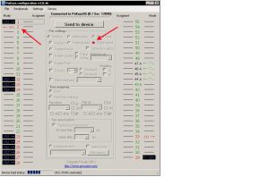
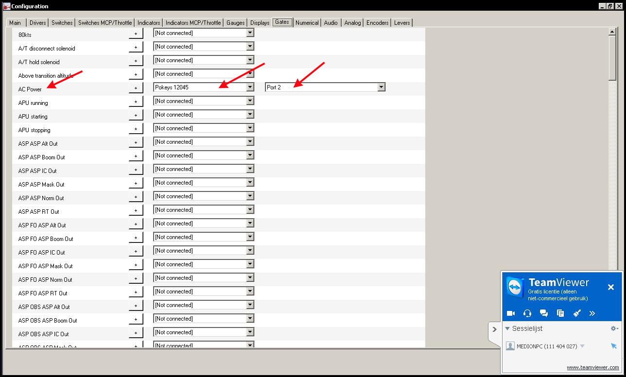
- If the Pokeys configuration software (Poscope) of the corresponding port as a digital Output (in this example, Port 2);
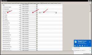
- Then, we will open Prosim737 Configuration – Gates, and we can select it in the list of "AC Power" followed by the appropriate Pokeysnr, and the right port (Port 2).
CONCLUSIONS
The price of the Custom Sim Parts-gauges are pretty cheap.
Custom Sim Parts, it is a very flexible and customer-friendly. The gauges are made in accordance with the requirements of the customer. So, I set up a Brake Pressure in a diamond shape, and the text " PSI " x 1000’ to change it to a blue colour.
The lead-time of 3 to 4 weeks to manufacture and dispatch of the order will be complied with.
The gauges of the CSP are beautiful and well made. The holes for the bevestigingsboutjes to sit in the right place, as it used to be, it is transmitted, and in which the fixing is very easy going. It is the same for all the different connections.
When you get to the configuration of the step-by-step photo's and video's to follow, this is an easy and simple task. A piece of cake ...
The backlighting of the gauges has to be realistic, and just wonderful to look at.
The needles or pointers on the gauges will move quickly and smoothly, without jerking.
The contacts with the Custom Sim Parts (Tom Kaminski) are easy to use and fast. He is very friendly to give advice or find solutions.
E-mails within a 24Hr to answer.
For me, this was a ‘try-out’project with the Custom Sim Parts a success all over the line.
Definitely a must-visit!


Translated by Yandex.Translate and Global Translator