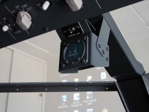
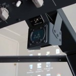
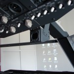
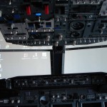
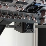
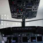
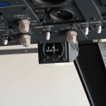
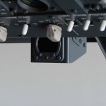
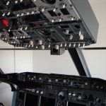
The Standby magnetic compass
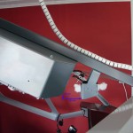
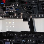
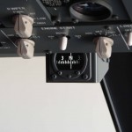
The Act, Compass, or an official of the Standby Magnetic Compass located directly behind the forward, overhead, and the upper edge of the glareshield.
This compass serves as a backup to X-check the information that is to be found in the glass of the displays.
This is the instrument for the flightsimmer is not really necessary, and it should be more like a complement of the interior of a home cockpit.
OPTIONS
For my homecockpit with the use of a compass, I had a choice of a few options :
- A kompasbehuizing (shell) with a built-in measuring scale and a needle with a backlightverlichting. This option looks at first glance to be realistic, and very cost-effective, but using a compass is that it is not working.
- A kompasbehuizing (shell) with a built-in mini monitor, and the associated graphics card. As with the first option you will also have to be realistic, and very cost-effective, and that, with the use of a compass that actually works.
- A kompasbehuizing with a built-in scale with a needle, steppermotor, controller for the steppermotor and the corresponding set of sensors. This concept is very real, but also complex to build. For the electronic whiz kids among us...
- A real compass on the head, tapping it on e-bay and convert it so that it is able to work with the FS and ProSim. This option is very realistic, but it is a lot more expensive, and you will need the instrument to get it to work ...
- A ‘ready made’ wet ' compass’ to buy in to the Flight Illusion. With this option, it will probably be the easiest solution but the most expensive. The 500 Euros that I have to use it for more important things in the cockpit.
.
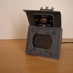
A photo of the original compass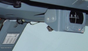
I opted for the second solution, namely the use of a the mini monitor.. The idea of a ‘NAX’ ( ProSim forum. ‘NAX’ has, however, opted for the option of using the steppermotor and sensors. A matter of choices ...
The option of the mini-unit : the First will be a kompasbehuizing (shell) is made of aluminum, and in this case, a monitor is placed in the + corresponding set of video controller card .
It is the intention of the ProSim-the compass to create an image (dragging) into the monitordisplay.
The cost : everything is included in between the 30 and € 50.
After carefully studying the pictures on the Airliners.net a couple of pictures of Martin van Liempt I was able to begin to see the breakdown.
During my research, I have noticed that there are 2 types of compass used to be. This is a different frontopbouw and related kompasschaalverdeling.
I'm the type that agrees with the ProSim Display Frontafbeelding, and scale).
COMPOSITION OF THE COMPASS
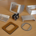
- Aluminum parts:
- A circular and a square front bezel made of plastic;
- Screws to attach the voorplaatjes;
- Monitordisplay with the video card and cables;
- Switch;
- Decal;
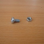
- Bolts and nuts should be used in order for the compass to be attached to the mounting bracket.
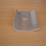
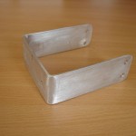
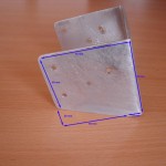
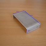
Aluminum parts
I've seen the case made out of aluminum 2 mm dimensions. These aluminum parts were scraps from the floor of my cockpit, which I had lying around. That will come in handy.
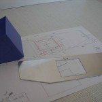
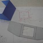
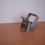
The compass shell is made up of 4 parts :
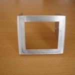
- The body is in the front and 2 sides
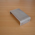
- A afdichtplaatje to the back side;
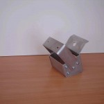
- The inclined portion for mounting an on / off switch that is located above the compass, that is.
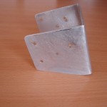
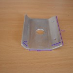
- A mounting bracket for the compass to be attached to the cockpitframe.
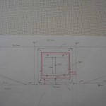
First of all I have everything covered and are designed for use on aluminum. Then, first, the hole in the middle cut out (the hole is a few mm larger than the LCD panel with a jigsaw, and then the rest of the aluminum parts. The plooiwerk is done between a pair of thick mdf panels.
The folds should, however, be kept in mind that the plooibocht in aluminum from time to time place (mm's) are taking ! Because of this, things can get wider ...
The edges and burrs, I covered it with a metaalvijl.
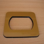
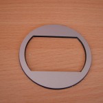
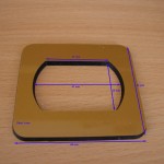
Plastic voorplaatjes
On the front, I have a square plate is glued on, followed by a circular plate with the same hole on top of it. The two plates are made from plastic or synthetic materials. These are the pictures + holes I have to create a local, an engraver, who, in the past, even with my MIP decals have been made.
In these pictures, I have small holes drilled in it where I cut the cups of the screws have been glued.
LCD monitor and video controller card
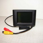
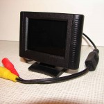
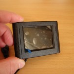
It says that I am the compass of a small 2.5-inch digital color LCD you can find it in the car. I bought it at eBay for a few dollars.
Technical data :
- TFT Dispaly mode: 320X240 pixels;
- Format:PAL or NTSC(Auto change);
- Power supple:DC8~12V;
- Power consumption:<5F;
- Auto save power function;
- Response time:25ms;
- 1 video input;
- Dimensions: - Length:85mm – Height:58mm(Without stand ),70mm(total height with stand);
- Thickness:20mm(H);
- Operating temperature:-10-+50;
- Storage: Storage temperature:-20-+60;
Switch and Decal
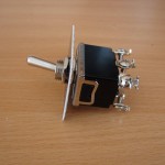
As a switch I have a switch, to buy. It is connected to ON/OFF.
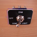
The decal with the text, I like my MIP decals or engraving. The achtzijde is double-sided adhesive tape.
The size of the decal include : 45 mm (W) x 35mm (H).
DIMENSIONS OF THE COMPASS SHELL
In these dimensions, the personal dimensions of that +- correspond to the dimensions of the other cockpitbouwers (eg. Martin Van Liempt – Eindhoven, The Netherlands.
The dimensions of the actual instrument is located in the vicinity of the +- To 70-mm to 80-mm if the width of the front and + 70 mm for the high altitude. Exact dimensions are not known to me.
This focus is perhaps a bit different from the real occurrence, because I have enough space (width) required for the installation of the video controller card.
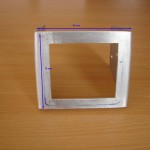
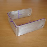
- Full-width-kompasframe (Body) : 220 mm;
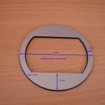
- Front : 80 mm (W front) x 70mm (H-front);
- Side : 70 mm (L) depth) x 70mm (H-front) and 50 mm (H rear), the oblique line bottom edge starting from the (15 mm);
- Cover to the rear panel 78 mm (W) x 43 mm (H), folded back portion at both sides. 2x 15 mm;
- Angled picture of the top for fixing the switch : 40 mm (H), folded back portion of the top 16 mm, folded back portion of getting to be attached to the body : 14 mm;
- Square front bezel : 65 mm (W) x 65 mm (H)one of the best dimensions of the opening : 47 mm (W) x 30mm (H);
- A circular front bezel : A Diameter of 58 mmone of the best dimensions of the opening : 47 mm (W) x 30mm (H);
- Head unit : 83 mm (W) x 98 mm (H) x 34 mm).
ASSEMBLY OF ALUMINIUM COMPONENTS
Everything is very simple and easy to implement. First of all the angled aluminum bovenplaatje is glued to the inside of the body. To do this, I have Tec7 use.
The circkelvormig front bezel is in the middle of the front edge of the squares with the picture glued on with superglue (or glue of your choice). It should be noted that the two holes in the middle, just to match.
In this voorplaatjes are holes to be drilled for the mounting of the boutkopjes (cups are cut from the bolts). The size of the book, it is your choice. This boutkopjes be fixed by adhesive in bore holes in it. This boutkopjes no bevestigingfunctie, and is only used as a ‘decoration’.
The whole of the bonded voorplaatjes in the middle of the front side of the body is glued together.
The afsluitplaatje the back is attached with screws, and matching nuts.
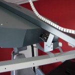
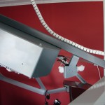
The aluminum bracket, which is the confirmation of the compass in the cockpit, that is at an oblique angle, bolted on (with the same type of bolts, nuts and screws) from each side of the compass shell (the body). The attachment of the mounting bracket in the cockpit, which depends on the individual capabilities of the built-up of a cockpit or a cockpitframe.
3 parts (body angled top and afsluitplaatje the reverse side) can now be made ready for painting.
The aluminum is first sanded with a fine sand paper (for metal). Also, the edges are sanded to make them nice and smooth.
After cleaning with spirits, are all in the primer set. After a sufficient (48 Hr) drying time, it can all be painted with the paint (RAL7011 or ACC, R6.06.30). In order to get a good cover, maybe 2 lakbeurten is required.
The ground and paint layers, I've done it with a can of spray paint. This gives a better and smoother result.
INSTALLATION OF THE LCD TO THE DISPLAY CONTROLLER CARD
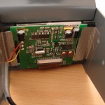
First, I took the monitor case (the shell) has been removed, as this is too much, place it in the compass. After I got this monitor case is removed to have the screen too close to the body down the line.
The opening on the front side of the aluminum body, I have a couple of mm larger than the size of the LCD screen. This is the window into the bore of the aluminum body to sit up.
Also, will the LCD screen be the of the squares the plastic front bezel and the view depth to the screen but it is small.
At first I used the controller card is attached to the back of the display with double-sided adhesive tape.
Then it was the turn of the screen+card to install in the kompasbehuizing (Shell).
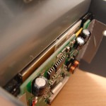
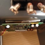
To the left and to the right on the inside of the body, there is a 10 mm insert in order to secure the video controller card. The LCD screen itself, zinc is practically complete in the hole of the aluminum body.
I have had the contents on the left and the right, in its inside, a plexiglass plate (10 mm x 45 mm x 3.5 mm) is attached. After that there are 2 strips of thick double sided tape to the plexi plates was applied.
Then it's time to use the card with the window down into the intended opening and along the two sides (that is, 10 mm, with acrylic panel + adhesive tape), and press it against the double-sided adhesive tape. All, I have to agree with both sides gesecured with Duct tape.
MOUNTING BRACKET
The mounting bracket is in the cockpitframe made with the 2 bolts. First, I've got 2 holes to be drilled and then tapped for the bolts.
Once the bracket is attached to the compass, it is hung and is held in place by 4 bolts with nut.
THE CONNECTIONS OF THE LCD MONITOR
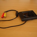
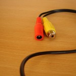
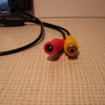
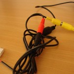
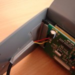
This is a mini-monitor that has a composite video connection (the YELLOW one), and a connector for the power supply (12 V)(RED).
Most of us are familiar with a graphics card, only the HDMI in, Display Port, VGA, and DVI port. However, on the older pc + graphics card, they also have a Composite or S-video connector on the video card, and that we usually are. In this case, it is useful to make use of them.
Now, years later, with the purchase of a new cockpitcomputers is that the new cards do not come equipped with a Composite video or S-video input terminal. A big problem, and so on ...
I happen to have from a person to an adapter to be able to receive the signal is transformed to VGA.
In the video, I have extended the central support beam of the dashboard is pulled up into the Forward Overhead.
The same goes for the power cable from the 12V from a pc power supply to the cockpit is the same road as in the video.
Also, you can monitor just use it as another VGA or DVI monitor. After this attached to your pc you can see it in your monitor setup in Windows.
The monitor should have a resolution of 320 x 240. The only resolution I can set is 640-by-480.
PROSIM, COMPASS
After starting ProSim and in the ProSim Compass is the compass in Window mode and drag it to the mini-monitor (the Compass) on top of the glareshield. It is only these zoom in and zoom out to the size you want and at the right place for you.
CONCLUSION
For very little money and a little bit of an artifact did you have in the Boeing cockpit, it is a good oogend while working ‘stand-by ' Compass’.
Translated by Yandex.Translate and Global Translator
